Matriks LED 8x8 Menggunakan Modul Arduino MAX7219
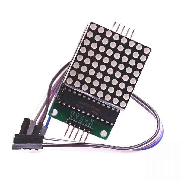
Dalam tutorial ini, kita akan belajar bagaimana mengontrol matriks LED 8x8 menggunakan modul MAX7219 dengan Arduino. MAX7219 menyederhanakan pengendalian beberapa LED, memungkinkan kita untuk menampilkan karakter dan pola dengan mudah. Pada akhir proyek ini, Anda akan dapat menampilkan kata "ROBOJAX" di matriks.
Untuk mencapai ini, kami akan memanfaatkan pustaka LedControl, yang dirancang khusus untuk berinteraksi dengan MAX7219. Pustaka ini memungkinkan kami mengirim data ke matriks LED dengan usaha minimal. Jika Anda ingin pemahaman yang lebih jelas tentang pengkabelan dan kode, pastikan untuk memeriksa video terkait (dalam video pada 0:30).
Penjelasan Perangkat Keras
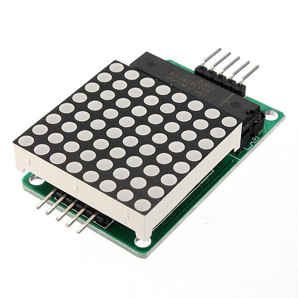
Komponen utama dari proyek ini termasuk modul MAX7219 dan matriks LED 8x8. MAX7219 adalah sirkuit terintegrasi yang mengelola tampilan LED, menangani komunikasi dan sinyal kontrol dari Arduino. Ini menggunakan antarmuka serial, yang berarti kita dapat mengontrol banyak LED hanya dengan beberapa pin dari Arduino.
Matriks LED 8x8 terdiri dari 64 LED individu yang disusun dalam sebuah grid. Setiap LED dapat dinyalakan atau dimatikan dengan mengirimkan perintah yang sesuai melalui MAX7219. Ini memungkinkan tampilan berbagai karakter dan grafik pada matriks.
Detail Lembar Data
| Produsen | Maxim Terintegrasi |
|---|---|
| Nomor bagian | MAX7219 |
| Tegangan Logika/IO | 3.3V hingga 5.5V |
| Tegangan suplai | 4.0V hingga 5.5V |
| Arus keluaran (per saluran) | 40 mA maks |
| Arus puncak (per saluran) | 100 mA maks |
| Panduan frekuensi PWM | 100 Hz |
| Ambang logika input | 2.0V (tinggi) / 0.8V (rendah) |
| Penurunan tegangan / RDS(on)/ saturasi | 0,2V typ. |
| Batas termal | 150°C |
| Paket | 16-DIP |
| Catatan / varian | Konfigurasi anoda umum |
- Pastikan pasokan daya yang tepat (4,0V hingga 5,5V).
- Gunakan resistor pembatas arus untuk setiap LED untuk mencegah kerusakan.
- Jaga kabel tetap pendek untuk menghindari gangguan.
- Pantau disipasi panas; gunakan heatsink jika perlu.
- Periksa kembali koneksi pin untuk menghindari kesalahan komunikasi.
Instruksi Pemasangan Kabel
Untuk menghubungkan MAX7219 ke Arduino, sambungkan pin-pin berikut:
- Sambungkanlah
VCCpin MAX7219 ke 5V Arduino. - Sambungkan
GNDsambungkan ke ground Arduino. - Sambungkan
DINpin (Data In) ke pin Arduino 12. - Sambungkan
CLKpin (Jam) ke pin Arduino 11. - Sambungkanlah
CSpin (Chip Select) ke pin Arduino 10.
Pastikan untuk memeriksa bahwa semua koneksi aman sebelum menyalakan sirkuit. Pemasangan kabelnya sederhana, tetapi jika Anda mengalami masalah, tinjau koneksi dengan cermat (dalam video pada 1:45).
Contoh Kode & Panduan
Dalam kode, kita mulai dengan menyertakan pustaka LedControl, yang penting untuk berkomunikasi dengan MAX7219. Cuplikan berikut menginisialisasi objek LedControl:
LedControl lc=LedControl(12,11,10,1);Baris ini mengatur pin data, pin jam, pin pemilih chip, dan jumlah perangkat (1, dalam hal ini). Selanjutnya, di dalamsetup()fungsi, kami menghidupkan MAX7219 dan mengatur intensitas tampilan:
lc.shutdown(0,false);
lc.setIntensity(0,8);
lc.clearDisplay(0);
Ini memastikan tampilan aktif dan siap untuk menampilkan karakter. Fungsi utama yang menggerakkan tampilan adalahwriteArduinoOnMatrix(), yang secara berurutan menyalakan baris-baris matriks untuk menampilkan huruf.
Demonstrasi / Apa yang Diharapkan
Setelah semuanya terhubung dan kode diunggah, matriks LED harus menampilkan kata "ROBOJAX". Jika tampilan tidak berfungsi, periksa masalah seperti koneksi yang longgar atau penugasan pin yang salah. Selain itu, pastikan pasokan daya memadai (dalam video pada 2:30).
Bab-bab
- Pengantar (0:00)
- Ikhtisar Perangkat Keras (0:30)
- Instruksi Pengkabelan (1:45)
- Panduan Kode (2:15)
- Demonstrasi (3:00)
Gambar
/*
 * This video shows you how to use the MAX7219 module with an 8x8 LED matrix to display text or any characters on the LED.
 * Watch YouTube video: https://youtu.be/AAiDwBKs9uE
 *
 * Written by Ahmad Shamshiri for Robojax.com
 * on February 26, 2017 in Ajax, Ontario, Canada
 * Get this code and other Arduino codes from Robojax.com
 * Learn Arduino step by step in a structured course with all materials, wiring diagrams, and libraries
 * all in one place.

 ****************************
 * Get early access to my videos via Patreon and have your name mentioned at the end of every
 * video I publish on YouTube here: http://robojax.com/L/?id=63 (watch until the end of this video for a list of my Patrons)
 ****************************

 * Or make a donation using PayPal http://robojax.com/L/?id=64

 * This code is "AS IS" without warranty or liability. Free to be used as long as you keep this note intact.
 * This code has been downloaded from Robojax.com
    This program is free software: you can redistribute it and/or modify
    it under the terms of the GNU General Public License as published by
    the Free Software Foundation, either version 3 of the License, or
    (at your option) any later version.

    This program is distributed in the hope that it will be useful,
    but WITHOUT ANY WARRANTY; without even the implied warranty of
    MERCHANTABILITY or FITNESS FOR A PARTICULAR PURPOSE.  See the
    GNU General Public License for more details.

    You should have received a copy of the GNU General Public License
    along with this program.  If not, see <https://www.gnu.org/licenses/>.
*/


// We always have to include the library
// Based on a project posted https://github.com/wayoda/LedControl
#include "LedControl.h"

 /*
  Now we need a LedControl to work with.
  // Customized for RoboJax.com on February 26, 2017 in Ajax, Ontario, Canada.
  ***** These pin numbers will probably not work with your hardware *****
  pin 12 is connected to the DataIn
  pin 11 is connected to the CLK
  pin 10 is connected to CS
  We have only a single MAX72XX.
  */
 LedControl lc=LedControl(12,11,10,1);

 /* we always wait a bit between updates of the display */
 unsigned long delaytime=600;

 void setup() {
   /*
    The MAX72XX is in power-saving mode on startup,
    we have to do a wakeup call
    */
   lc.shutdown(0,false);
   /* Set the brightness to a medium value */
   lc.setIntensity(0,8);
   /* and clear the display */
   lc.clearDisplay(0);
 }

 /*
  This method will display the characters for the
  word "Arduino" one after the other on the matrix.
  (you need at least 5x7 LEDs to see the whole characters)
  */
 void writeArduinoOnMatrix() {
   /* here is the data for the characters */

   // K
   byte R[8]={B11111100,B10000100,B10000100,B11111000,B10100000,B10010000,B10001000,B10000100};
   byte O[8]={B00011000,B00100100,B01000010,B01000010,B01000010,B01000010,B00100100,B00011000};
   byte B[8]={B11111100,B10000100,B10000100,B11111000,B10001000,B10000100,B10000100,B11111100};
   byte J[8]={B00011110,B00000100,B00000100,B00000100,B10000100,B10000100,B01000100,B00111000};
   byte A[8]={B00111000,B01000100,B10000010,B11111110,B10000010,B10000010,B10000010,B10000010};
   byte X[8]={ B10000001,B01000010,B00100100,B00011000,B00011000,B00100100,B01000010,B10000001};
   byte love[8]={ B00000000,B01100110,B10011001,B10011001,B10000001,B01000010,B00100100,B00011000};


   /* Letter R */
   for (int i=0; i<8; i++){
   lc.setRow(0,i,R[i]);

   }

   delay(delaytime);
   for(int i=0; i<8; i++){
       lc.setRow(0,i,0);// this is for blank
   }
 //////////////// END of Letter R ///////

   /* Letter O */
   for (int i=0; i<8; i++){
   lc.setRow(0,i,O[i]);

   }

   delay(delaytime);
   for(int i=0; i<8; i++){
       lc.setRow(0,i,0);// this is for blank
   }
 //////////////// END of Letter O ///////


   /* Letter B */
   for (int i=0; i<8; i++){
   lc.setRow(0,i,B[i]);

   }

   delay(delaytime);
   for(int i=0; i<8; i++){
       lc.setRow(0,i,0);// this is for blank
   }
 //////////////// END of Letter B ///////

   /* Letter O */
   for (int i=0; i<8; i++){
   lc.setRow(0,i,O[i]);

   }

   delay(delaytime);
   for(int i=0; i<8; i++){
       lc.setRow(0,i,0);// this is for blank
   }
 //////////////// END of Letter O ///////

   /* Letter J */
   for (int i=0; i<8; i++){
   lc.setRow(0,i,J[i]);

   }

   delay(delaytime);
   for(int i=0; i<8; i++){
       lc.setRow(0,i,0);// this is for blank
   }
 //////////////// END of Letter J ///////

   /* Letter A */
   for (int i=0; i<8; i++){
   lc.setRow(0,i,A[i]);

   }

   delay(delaytime);
   for(int i=0; i<8; i++){
       lc.setRow(0,i,0);// this is for blank
   }
 //////////////// END of Letter A ///////

   /* Letter X */
   for (int i=0; i<8; i++){
   lc.setRow(0,i,X[i]);

   }

   delay(delaytime);
   for(int i=0; i<8; i++){
       lc.setRow(0,i,0);// this is for blank
   }
 //////////////// END of Letter X ///////


   /* love */
   for (int i=0; i<8; i++){
   lc.setRow(0,i,love[i]);

   }

   delay(delaytime);
   delay(delaytime);
   for(int i=0; i<8; i++){
       lc.setRow(0,i,0);// this is for blank
   }
 //////////////// END of Letter love ///////

 }// writeArduinoOnMatrix()  end


 void loop() {
   writeArduinoOnMatrix();

}/*
* This video shows you how to use the MAX7219 module with an 8x8 LED matrix to display text or any characters on the LED.
* Watch YouTube video: https://youtu.be/AAiDwBKs9uE
*
* Written by Ahmad S. for Robojax.com
* on February 26, 2017 in Ajax, Ontario, Canada
* Permission granted to share this code, given that this
* note is kept with the code.
* Disclaimer: This code is "AS IS" and for educational purposes only.
*/
// We always have to include the library
// Based on a project posted on https://github.com/wayoda/LedControl
#include "LedControl.h"
/*
Now we need a LedControl object to work with.
// Customized for RoboJax.com on February 26, 2017 in Ajax, Ontario, Canada.
***** These pin numbers will probably not work with your hardware *****
pin 1 is connected to the DataIn
pin 4 is connected to the CLK
pin 53 is connected to CS
We have only a single MAX72XX.
*/
LedControl lc=LedControl(1,4,53,1);// this line determines if this code can work with Arduino Mega or Arduino UNO
/* we always wait a bit between updates of the display */
unsigned long delaytime=600;
void setup() {
/*
The MAX72XX is in power-saving mode on startup,
we have to do a wakeup call
*/
lc.shutdown(0,false);
/* Set the brightness to a medium value */
lc.setIntensity(0,8);
/* and clear the display */
lc.clearDisplay(0);
}
/*
This method will display the characters for the
word "Arduino" one after the other on the matrix.
(you need at least 5x7 LEDs to see the whole characters)
*/
void writeArduinoOnMatrix() {
/* here is the data for the characters */
// K
byte R[8]={B11111100,B10000100,B10000100,B11111000,B10100000,B10010000,B10001000,B10000100};
byte O[8]={B00011000,B00100100,B01000010,B01000010,B01000010,B01000010,B00100100,B00011000};
byte B[8]={B11111100,B10000100,B10000100,B11111000,B10001000,B10000100,B10000100,B11111100};
byte J[8]={B00011110,B00000100,B00000100,B00000100,B10000100,B10000100,B01000100,B00111000};
byte A[8]={B00111000,B01000100,B10000010,B11111110,B10000010,B10000010,B10000010,B10000010};
byte X[8]={ B10000001,B01000010,B00100100,B00011000,B00011000,B00100100,B01000010,B10000001};
byte love[8]={ B00000000,B01100110,B10011001,B10011001,B10000001,B01000010,B00100100,B00011000};
/* Letter R */
for (int i=0; i<8; i++){
lc.setRow(0,i,R[i]);
}
delay(delaytime);
for(int i=0; i<8; i++){
lc.setRow(0,i,0);// this is for blank
}
/////////////// END of Letter R ///////
/* Letter O */
for (int i=0; i<8; i++){
lc.setRow(0,i,O[i]);
}
delay(delaytime);
for(int i=0; i<8; i++){
lc.setRow(0,i,0);// this is for blank
}
/////////////// END of Letter O ///////
/* Letter B */
for (int i=0; i<8; i++){
lc.setRow(0,i,B[i]);
}
delay(delaytime);
for(int i=0; i<8; i++){
lc.setRow(0,i,0);// this is for blank
}
/////////////// END of Letter B ///////
/* Letter O */
for (int i=0; i<8; i++){
lc.setRow(0,i,O[i]);
}
delay(delaytime);
for(int i=0; i<8; i++){
lc.setRow(0,i,0);// this is for blank
}
/////////////// END of Letter O ///////
/* Letter J */
for (int i=0; i<8; i++){
lc.setRow(0,i,J[i]);
}
delay(delaytime);
for(int i=0; i<8; i++){
lc.setRow(0,i,0);// this is for blank
}
/////////////// END of Letter J ///////
/* Letter A */
for (int i=0; i<8; i++){
lc.setRow(0,i,A[i]);
}
delay(delaytime);
for(int i=0; i<8; i++){
lc.setRow(0,i,0);// this is for blank
}
/////////////// END of Letter A ///////
/* Letter X */
for (int i=0; i<8; i++){
lc.setRow(0,i,X[i]);
}
delay(delaytime);
for(int i=0; i<8; i++){
lc.setRow(0,i,0);// this is for blank
}
/////////////// END of Letter X ///////
/* love */
for (int i=0; i<8; i++){
lc.setRow(0,i,love[i]);
}
delay(delaytime);
delay(delaytime);
for(int i=0; i<8; i++){
lc.setRow(0,i,0);// this is for blank
}
/////////////// END of love ///////
}// writeArduinoOnMatrix() end
void loop() {
writeArduinoOnMatrix();
}Hal-hal yang mungkin Anda butuhkan
-
AmazonMax7219 8x8 Matrix on Amazonamzn.to
-
eBayMax7219 8x8 Matrix on eBayebay.us
-
AliExpressMax7219 8x8 Matrix on AliExpresss.click.aliexpress.com
Sumber daya & referensi
-
DokumentasiView different board pin assignments for SPIarduino.cc
-
Eksternal
Berkas📁
File lainnya
-
Perpustakaan Matriks MAX7219 dari Robojax
robojax-MAX7219-matrix.zip0.01 MB -
8-Digit LED Display Library (from Robojax.com)
robojax_MAX7291_8_digits.zip