8x8 LED-matrix met 'n MAX7219 Arduino-module
In hierdie tutorial sal ons leer hoe om 'n 8x8 LED-matrix te beheer met 'n MAX7219-module saam met 'n Arduino. Die MAX7219 vereenvoudig die beheer van verskeie LED's, wat ons in staat stel om karakters en patrone maklik te vertoon. Teen die einde van hierdie projek sal jy in staat wees om die woord "ROBOJAX" op die matrix te vertoon.
Om dit te bereik, sal ons die LedControl-biblioteek gebruik, wat spesifiek ontwerp is om met die MAX7219 te kommunikeer. Hierdie biblioteek stel ons in staat om data na die LED-matrix te stuur met minimale moeite. As jy 'n duideliker begrip van die bedrading en kode wil hê, maak seker om die verwante video te kyk (in video by 0:30).
Hardeware verduidelik
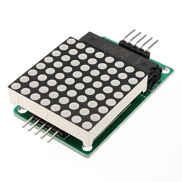
Die primêre komponente van hierdie projek sluit die MAX7219-module en die 8x8 LED-matrix in. Die MAX7219 is 'n geïntegreerde stroombaan wat die vertoning van die LED's bestuur, en die kommunikasie- en beheersignale van die Arduino hanteer. Dit gebruik 'n seriële koppelvlak, wat beteken dat ons baie LED's met net 'n paar penne van die Arduino kan beheer.
Die 8x8 LED-matrix bestaan uit 64 individuele LED's wat in 'n rooster gerangskik is. Elke LED kan aangeskakel of afgeskakel word deur die toepaslike opdragte deur die MAX7219 te stuur. Dit maak dit moontlik om verskillende karakters en grafika op die matriks te vertoon.
Datasheet Besonderhede
| Fabrikant | Maxim Geintegreer |
|---|---|
| Onderdeel nommer | MAX7219 |
| Logika/IO spanning | 3.3V tot 5.5V |
| Voorsienings spanning | 4.0V tot 5.5V |
| Uitsetstroom (per kanaal) | 40 mA maks |
| Piekstroom (per kanaal) | 100 mA maks |
| PWM frekwensie riglyne | 100 Hz |
| Invoerlingsdrempels | 2.0V (hoog) / 0.8V (laag) |
| Spanningstoename / RDS(on)/ versadiging | 0.2V tip. |
| Termiese perke | 150°C |
| Pakket | 16-DIP |
| Notas / variante | Algemene anodekonfigurasie |
- Verseker 'n behoorlike kragtoevoer (4.0V tot 5.5V).
- Gebruik huidige-beperkende weerstande vir elke LED om skade te voorkom.
- Hou die bedrading kort om interferensie te vermy.
- Monitor hitte-afvoer; gebruik 'n hitte-sink indien nodig.
- Dubbelkontroleer penverbindinge om miskommunikasie te vermy.
Draadinstruksies
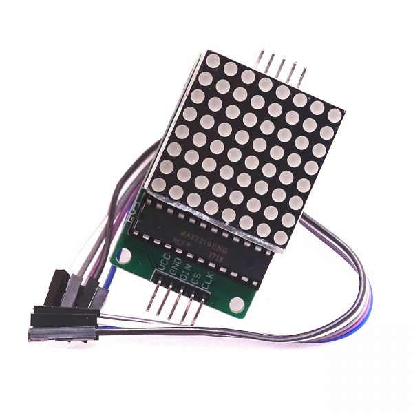
Om die MAX7219 aan die Arduino te koppel, verbind die volgende penne:
- Koppel die
VCCpen van die MAX7219 na die Arduino se 5V. - Koppel die
GNDpen na die Arduino se grond. - Koppel die
DINpen (Data In) na Arduino pen 12. - Koppel die
CLKpen (Horlosie) na Arduino pen 11. - Koppel die
CSpen (Chip Select) na Arduino pen 10.
Maak seker dat jy al die verbindings veilig maak voordat jy die stroombaan aan die gang sit. Die bedrading is eenvoudig, maar as jy probleme ondervind, hersien die verbindings sorgvuldig (in die video op 1:45).
Kode Voorbeelde & Staproete
In die kode begin ons deur die LedControl-biblioteek in te sluit, wat noodsaaklik is vir kommunikasie met die MAX7219. Die volgende uittreksel inisieer die LedControl-objek:
LedControl lc=LedControl(12,11,10,1);Hierdie lyn stel die datapin, klokpin, skyfkeusepin en die aantal toestelle (1, in hierdie geval) in. Volgende, in diesetup()funksie, ons wek die MAX7219 op en stel die vertoonintensiteit in:
lc.shutdown(0,false);
lc.setIntensity(0,8);
lc.clearDisplay(0);
Dit verseker dat die vertoon aktief is en gereed is om karakters te wys. Die hooffunksie wat die vertoon dryf, iswriteArduinoOnMatrix(), wat die rye van die matriks een vir een verlig om letters te vertoon.
Demonstraie / Wat om te verwag
Sodra alles bedraad is en die kode opgelaai is, moet die LED-matrix die woord "ROBOJAX" vertoon. As die vertoning nie werk nie, kyk vir probleme soos los verbindings of verkeerde pen toewysings. Verseker ook dat die kragtoevoer voldoende is (in die video om 2:30).
Hoofstukke
- Inleiding (0:00)
- Hardeware Oorsig (0:30)
- Draadinstruksies (1:45)
- Kode Deurloop (2:15)
- Demonstraasie (3:00)
Beelde
/*
 * This video shows you how to use the MAX7219 module with an 8x8 LED matrix to display text or any characters on the LED.
 * Watch YouTube video: https://youtu.be/AAiDwBKs9uE
 *
 * Written by Ahmad Shamshiri for Robojax.com
 * on February 26, 2017 in Ajax, Ontario, Canada
 * Get this code and other Arduino codes from Robojax.com
 * Learn Arduino step by step in a structured course with all materials, wiring diagrams, and libraries
 * all in one place.

 ****************************
 * Get early access to my videos via Patreon and have your name mentioned at the end of every
 * video I publish on YouTube here: http://robojax.com/L/?id=63 (watch until the end of this video for a list of my Patrons)
 ****************************

 * Or make a donation using PayPal http://robojax.com/L/?id=64

 * This code is "AS IS" without warranty or liability. Free to be used as long as you keep this note intact.
 * This code has been downloaded from Robojax.com
    This program is free software: you can redistribute it and/or modify
    it under the terms of the GNU General Public License as published by
    the Free Software Foundation, either version 3 of the License, or
    (at your option) any later version.

    This program is distributed in the hope that it will be useful,
    but WITHOUT ANY WARRANTY; without even the implied warranty of
    MERCHANTABILITY or FITNESS FOR A PARTICULAR PURPOSE.  See the
    GNU General Public License for more details.

    You should have received a copy of the GNU General Public License
    along with this program.  If not, see <https://www.gnu.org/licenses/>.
*/


// We always have to include the library
// Based on a project posted https://github.com/wayoda/LedControl
#include "LedControl.h"

 /*
  Now we need a LedControl to work with.
  // Customized for RoboJax.com on February 26, 2017 in Ajax, Ontario, Canada.
  ***** These pin numbers will probably not work with your hardware *****
  pin 12 is connected to the DataIn
  pin 11 is connected to the CLK
  pin 10 is connected to CS
  We have only a single MAX72XX.
  */
 LedControl lc=LedControl(12,11,10,1);

 /* we always wait a bit between updates of the display */
 unsigned long delaytime=600;

 void setup() {
   /*
    The MAX72XX is in power-saving mode on startup,
    we have to do a wakeup call
    */
   lc.shutdown(0,false);
   /* Set the brightness to a medium value */
   lc.setIntensity(0,8);
   /* and clear the display */
   lc.clearDisplay(0);
 }

 /*
  This method will display the characters for the
  word "Arduino" one after the other on the matrix.
  (you need at least 5x7 LEDs to see the whole characters)
  */
 void writeArduinoOnMatrix() {
   /* here is the data for the characters */

   // K
   byte R[8]={B11111100,B10000100,B10000100,B11111000,B10100000,B10010000,B10001000,B10000100};
   byte O[8]={B00011000,B00100100,B01000010,B01000010,B01000010,B01000010,B00100100,B00011000};
   byte B[8]={B11111100,B10000100,B10000100,B11111000,B10001000,B10000100,B10000100,B11111100};
   byte J[8]={B00011110,B00000100,B00000100,B00000100,B10000100,B10000100,B01000100,B00111000};
   byte A[8]={B00111000,B01000100,B10000010,B11111110,B10000010,B10000010,B10000010,B10000010};
   byte X[8]={ B10000001,B01000010,B00100100,B00011000,B00011000,B00100100,B01000010,B10000001};
   byte love[8]={ B00000000,B01100110,B10011001,B10011001,B10000001,B01000010,B00100100,B00011000};


   /* Letter R */
   for (int i=0; i<8; i++){
   lc.setRow(0,i,R[i]);

   }

   delay(delaytime);
   for(int i=0; i<8; i++){
       lc.setRow(0,i,0);// this is for blank
   }
 //////////////// END of Letter R ///////

   /* Letter O */
   for (int i=0; i<8; i++){
   lc.setRow(0,i,O[i]);

   }

   delay(delaytime);
   for(int i=0; i<8; i++){
       lc.setRow(0,i,0);// this is for blank
   }
 //////////////// END of Letter O ///////


   /* Letter B */
   for (int i=0; i<8; i++){
   lc.setRow(0,i,B[i]);

   }

   delay(delaytime);
   for(int i=0; i<8; i++){
       lc.setRow(0,i,0);// this is for blank
   }
 //////////////// END of Letter B ///////

   /* Letter O */
   for (int i=0; i<8; i++){
   lc.setRow(0,i,O[i]);

   }

   delay(delaytime);
   for(int i=0; i<8; i++){
       lc.setRow(0,i,0);// this is for blank
   }
 //////////////// END of Letter O ///////

   /* Letter J */
   for (int i=0; i<8; i++){
   lc.setRow(0,i,J[i]);

   }

   delay(delaytime);
   for(int i=0; i<8; i++){
       lc.setRow(0,i,0);// this is for blank
   }
 //////////////// END of Letter J ///////

   /* Letter A */
   for (int i=0; i<8; i++){
   lc.setRow(0,i,A[i]);

   }

   delay(delaytime);
   for(int i=0; i<8; i++){
       lc.setRow(0,i,0);// this is for blank
   }
 //////////////// END of Letter A ///////

   /* Letter X */
   for (int i=0; i<8; i++){
   lc.setRow(0,i,X[i]);

   }

   delay(delaytime);
   for(int i=0; i<8; i++){
       lc.setRow(0,i,0);// this is for blank
   }
 //////////////// END of Letter X ///////


   /* love */
   for (int i=0; i<8; i++){
   lc.setRow(0,i,love[i]);

   }

   delay(delaytime);
   delay(delaytime);
   for(int i=0; i<8; i++){
       lc.setRow(0,i,0);// this is for blank
   }
 //////////////// END of Letter love ///////

 }// writeArduinoOnMatrix()  end


 void loop() {
   writeArduinoOnMatrix();

}/*
* This video shows you how to use the MAX7219 module with an 8x8 LED matrix to display text or any characters on the LED.
* Watch YouTube video: https://youtu.be/AAiDwBKs9uE
*
* Written by Ahmad S. for Robojax.com
* on February 26, 2017 in Ajax, Ontario, Canada
* Permission granted to share this code, given that this
* note is kept with the code.
* Disclaimer: This code is "AS IS" and for educational purposes only.
*/
// We always have to include the library
// Based on a project posted on https://github.com/wayoda/LedControl
#include "LedControl.h"
/*
Now we need a LedControl object to work with.
// Customized for RoboJax.com on February 26, 2017 in Ajax, Ontario, Canada.
***** These pin numbers will probably not work with your hardware *****
pin 1 is connected to the DataIn
pin 4 is connected to the CLK
pin 53 is connected to CS
We have only a single MAX72XX.
*/
LedControl lc=LedControl(1,4,53,1);// this line determines if this code can work with Arduino Mega or Arduino UNO
/* we always wait a bit between updates of the display */
unsigned long delaytime=600;
void setup() {
/*
The MAX72XX is in power-saving mode on startup,
we have to do a wakeup call
*/
lc.shutdown(0,false);
/* Set the brightness to a medium value */
lc.setIntensity(0,8);
/* and clear the display */
lc.clearDisplay(0);
}
/*
This method will display the characters for the
word "Arduino" one after the other on the matrix.
(you need at least 5x7 LEDs to see the whole characters)
*/
void writeArduinoOnMatrix() {
/* here is the data for the characters */
// K
byte R[8]={B11111100,B10000100,B10000100,B11111000,B10100000,B10010000,B10001000,B10000100};
byte O[8]={B00011000,B00100100,B01000010,B01000010,B01000010,B01000010,B00100100,B00011000};
byte B[8]={B11111100,B10000100,B10000100,B11111000,B10001000,B10000100,B10000100,B11111100};
byte J[8]={B00011110,B00000100,B00000100,B00000100,B10000100,B10000100,B01000100,B00111000};
byte A[8]={B00111000,B01000100,B10000010,B11111110,B10000010,B10000010,B10000010,B10000010};
byte X[8]={ B10000001,B01000010,B00100100,B00011000,B00011000,B00100100,B01000010,B10000001};
byte love[8]={ B00000000,B01100110,B10011001,B10011001,B10000001,B01000010,B00100100,B00011000};
/* Letter R */
for (int i=0; i<8; i++){
lc.setRow(0,i,R[i]);
}
delay(delaytime);
for(int i=0; i<8; i++){
lc.setRow(0,i,0);// this is for blank
}
/////////////// END of Letter R ///////
/* Letter O */
for (int i=0; i<8; i++){
lc.setRow(0,i,O[i]);
}
delay(delaytime);
for(int i=0; i<8; i++){
lc.setRow(0,i,0);// this is for blank
}
/////////////// END of Letter O ///////
/* Letter B */
for (int i=0; i<8; i++){
lc.setRow(0,i,B[i]);
}
delay(delaytime);
for(int i=0; i<8; i++){
lc.setRow(0,i,0);// this is for blank
}
/////////////// END of Letter B ///////
/* Letter O */
for (int i=0; i<8; i++){
lc.setRow(0,i,O[i]);
}
delay(delaytime);
for(int i=0; i<8; i++){
lc.setRow(0,i,0);// this is for blank
}
/////////////// END of Letter O ///////
/* Letter J */
for (int i=0; i<8; i++){
lc.setRow(0,i,J[i]);
}
delay(delaytime);
for(int i=0; i<8; i++){
lc.setRow(0,i,0);// this is for blank
}
/////////////// END of Letter J ///////
/* Letter A */
for (int i=0; i<8; i++){
lc.setRow(0,i,A[i]);
}
delay(delaytime);
for(int i=0; i<8; i++){
lc.setRow(0,i,0);// this is for blank
}
/////////////// END of Letter A ///////
/* Letter X */
for (int i=0; i<8; i++){
lc.setRow(0,i,X[i]);
}
delay(delaytime);
for(int i=0; i<8; i++){
lc.setRow(0,i,0);// this is for blank
}
/////////////// END of Letter X ///////
/* love */
for (int i=0; i<8; i++){
lc.setRow(0,i,love[i]);
}
delay(delaytime);
delay(delaytime);
for(int i=0; i<8; i++){
lc.setRow(0,i,0);// this is for blank
}
/////////////// END of love ///////
}// writeArduinoOnMatrix() end
void loop() {
writeArduinoOnMatrix();
}Goedere wat jy dalk nodig het
-
AmazonMax7219 8x8 Matrix on Amazonamzn.to
-
eBayMax7219 8x8 Matrix on eBayebay.us
-
AliExpressMax7219 8x8 Matrix on AliExpresss.click.aliexpress.com
Hulpbronne en verwysings
-
DokumentasieView different board pin assignments for SPIarduino.cc
-
Buitenburg
Lêers📁
Ander lêers
-
MAX7219 Matrix Library from Robojax
robojax-MAX7219-matrix.zip0.01 MB -
8-Digit LED Display Library (from Robojax.com)
robojax_MAX7291_8_digits.zip