How to use the XH-M603 Battery Protection Controller Module
In this tutorial, we will explore the XH-M603 battery protection controller module designed for managing lead-acid battery charging. This module allows you to connect a charger or solar panel to effectively charge your battery while safeguarding it from overcharging. By the end of this guide, you will have a clear understanding of how to wire and configure this module for optimal performance.
For clarity on the setup and operation, I encourage you to watch the associated video at (in video at 00:00). This video provides step-by-step instructions and visual aids that will enhance your understanding of the module's functionality.
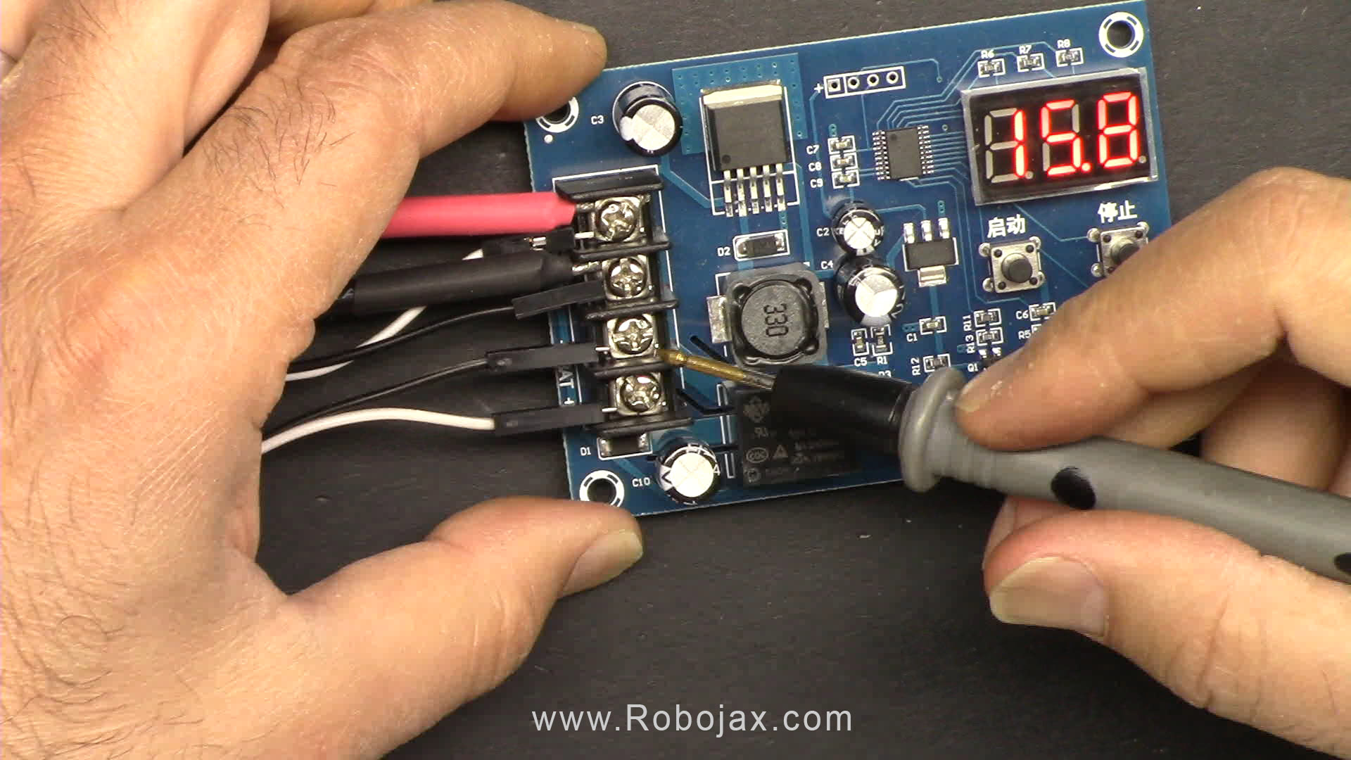
Hardware Explained
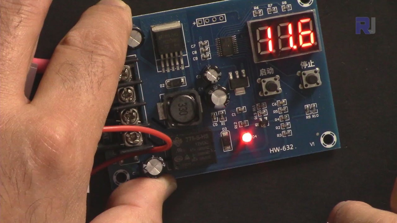
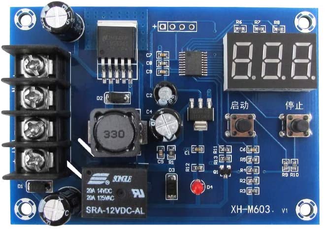
The XH-M603 module consists of several key components that work together to manage the charging process. The main features include a relay, which connects and disconnects the charger based on the voltage thresholds you set, and a microcontroller that monitors battery voltage. Additionally, the module includes voltage regulators to ensure consistent output for the microcontroller and display.
One important aspect of this module is the LM2596 step-down converter, which adjusts the input voltage to a stable output voltage for the battery. It is crucial to ensure that the wiring is robust enough to handle the current without overheating, especially since this module can manage significant loads.
Datasheet Details
| Manufacturer | Unknown |
|---|---|
| Part number | XH-M603 |
| Input voltage range | 12–30 V |
| Output voltage | 12 V (fixed) |
| Relay rating | 10 A max |
| Battery types | Lead Acid |
| Current handling | Up to 60 A (with proper wiring) |
| Control method | Voltage-based |
| Dimensions | 82 x 58.2 x 19.6 mm |
| Notes / variants | Different versions may exist |
- Ensure the relay is rated for the voltage and current of your application.
- Use thick wires to minimize resistance and heat generation.
- Monitor the voltage levels to prevent battery damage.
- Set the start and stop voltages carefully.
- Be aware of the maximum input voltage limits (30 V).
- Factory reset can be done by holding both buttons during power-up.
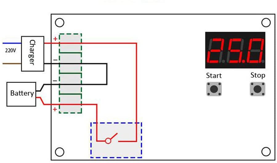
Wiring Instructions
Wiring the XH-M603 module is straightforward. First, connect your charger or solar panel to the designated input terminals on the module, ensuring that the positive lead connects to the input positive terminal and the negative lead to the input negative terminal. Next, connect the lead-acid battery to the output terminals, again making sure that the positive lead goes to the output positive terminal and the negative lead to the output negative terminal.
For optimal performance, use thick gauge wire to connect all terminals, especially for the battery connections, as this will help handle the high current loads without overheating. Pay attention to the relay connections; the relay should only be used for DC voltage applications as specified by the module's rating. If you see any discrepancies in voltage readings during your tests, double-check all your connections to ensure they are secure and correctly placed.
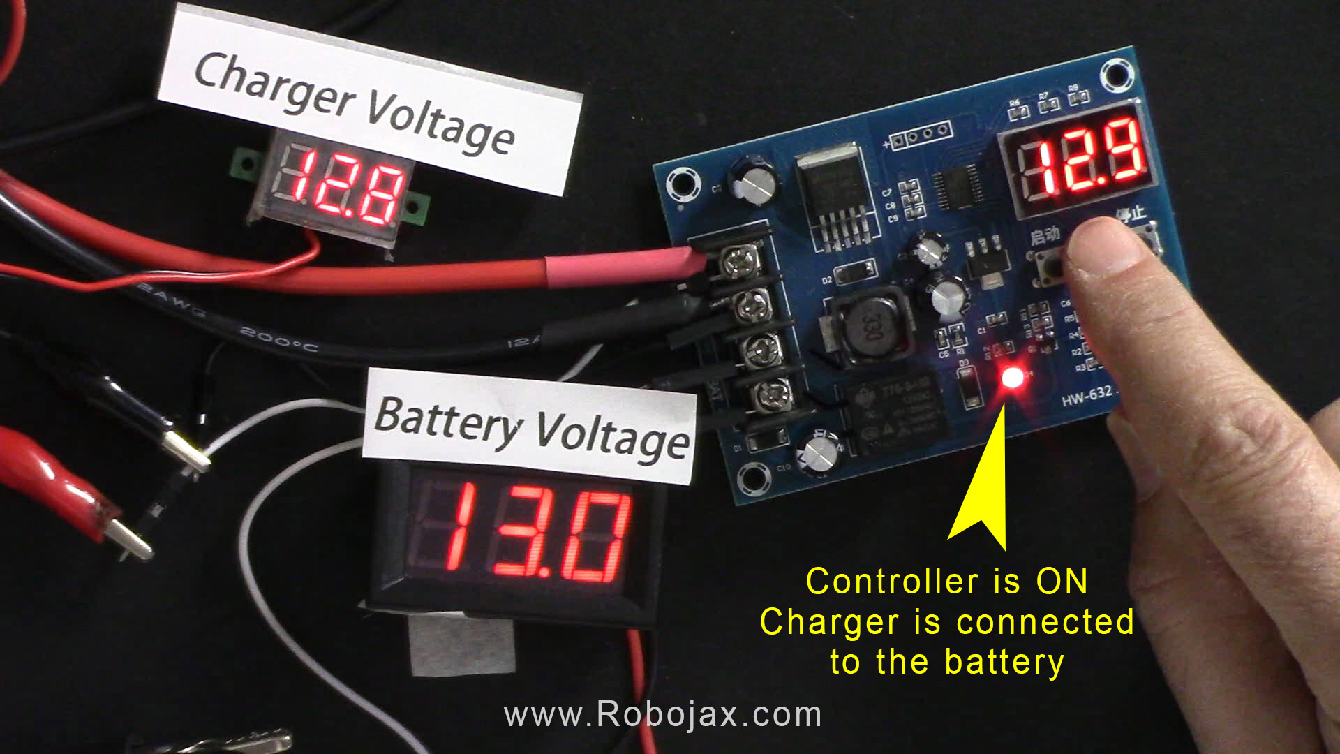
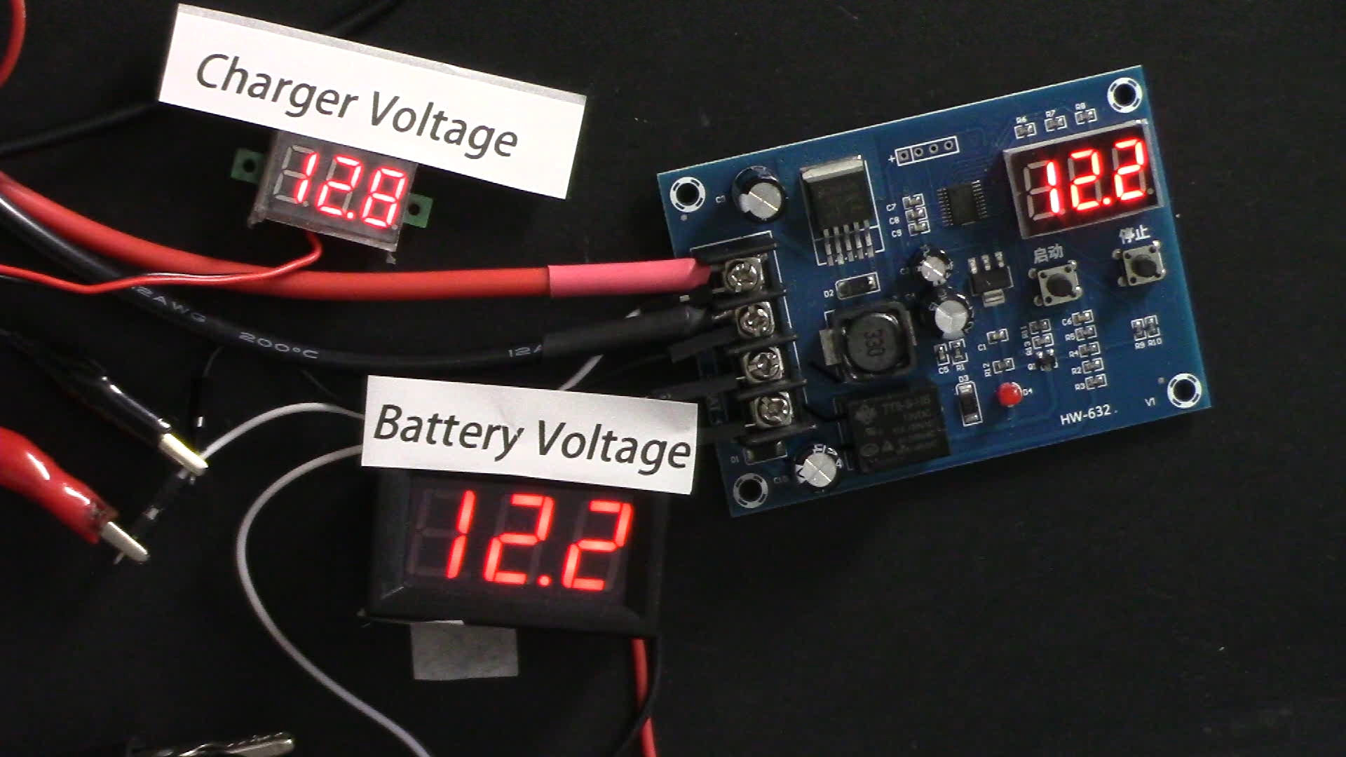
Demonstration / What to Expect
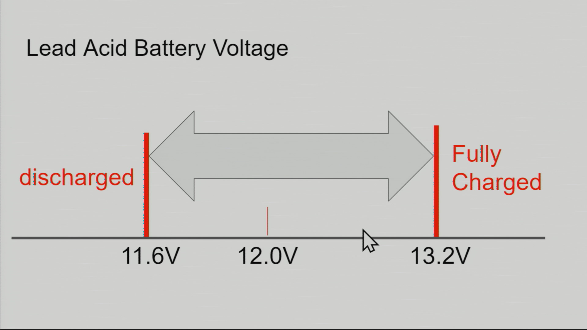
When properly wired and configured, the XH-M603 module will effectively manage the charging of your lead-acid battery. You should see the relay engage when the battery voltage drops below your set startVoltage (e.g., 11.6V). As the battery charges and reaches the stopVoltage (e.g., 13.2V), the relay will disengage, preventing overcharging. If you encounter issues such as the relay not activating, check your voltage settings and ensure that the battery is within the specified range (in video at 14:30).
Video Timestamps
- 00:00 Start
- 00:26 Introduction
- 01:22 HX-W603 Explained
- 05:53 Settings of the module
- 09:41 Setting factory defaults
- 10:40 Demonstration of charging a battery
- 15:08 Calculating Charging Time
Images
Things you might need
-
eBayXH-M603 on eBayebay.us
-
AliExpressXH-M603 on AliExpresss.click.aliexpress.com
-
BanggoodXH-M603 on Banggoodbanggood.com
Resources & references
-
ExternalAMS1117 5V regulator datasheet (PDF)advanced-monolithic.com
-
External
-
External
-
ExternalSS34 Diode Datasheet (PDF)vishay.com
-
ExternalXH-M603 on AliExpresss.click.aliexpress.com
-
ExternalXH-M603 on Amazonamzn.to
-
ExternalXH-M603 on Banggoodbanggood.com
-
ExternalXH-M603 on eBayebay.us
Files📁
No files available.