Código Arduino e vídeo para display OLED SSD1306 128 x 64
Neste tutorial, exploraremos como usar o display SSD1306 OLED 128 x 64 com um Arduino. O SSD1306 é um display versátil que permite exibir texto, gráficos e várias formas com facilidade. Ao final deste artigo, você será capaz de configurar o display e executar código que demonstre suas capacidades.

Vamos guiá-lo pelas conexões de hardware necessárias e fornecer trechos de código para ajudá-lo a entender os principais identificadores usados no programa. Para uma explicação mais visual, não deixe de assistir ao vídeo associado (no vídeo em 00:00).
Hardware Explicado
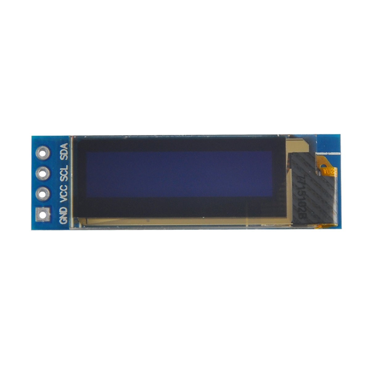
Os componentes principais deste projeto incluem a placa Arduino e o módulo de display OLED SSD1306. O display SSD1306 utiliza o protocolo de comunicação I2C, o que simplifica a fiação ao exigir apenas duas linhas de dados: SDA para dados e SCL para o sinal de clock. O display opera em tensões entre 3.3V e 5V, tornando-o compatível com a maioria das placas Arduino.
Além do display, você precisará de fios jumper para conectar o módulo ao seu Arduino. As conexões incluem VCC para alimentação, GND para massa, SDA para o pino de dados do Arduino e SCL para o pino de clock. Essa configuração permite comunicação fácil entre o Arduino e o display OLED.
Detalhes da ficha técnica
| Fabricante | Adafruit |
|---|---|
| Número da peça | SSD1306 |
| Tensão de lógica/E/S | 3.3 V - 5 V |
| Tensão de alimentação | 3.3 V - 5 V |
| Resolução do ecrã | 128 x 64 pixels |
| Endereço I2C | 0x3C |
| Interface | I2C |
| Pacote | Módulo |
- Certifique-se da ligação correta: VCC a 3.3V ou 5V, GND ao terra, SDA no pino A4, SCL no pino A5 (no Arduino Uno).
- O display requer resistores pull-up nas linhas SDA e SCL caso estes não estejam já incluídos.
- Verifique se o endereço I2C está definido corretamente no código, normalmente 0x3C para este display.
- Use uma biblioteca adequada, como a Adafruit_SSD1306, para facilitar a integração.
- Limpe a tela antes de desenhar novos gráficos para evitar artefatos de sobreposição.
Instruções de Fiação

Para ligar o display OLED SSD1306 ao seu Arduino, siga estes passos:
Conecte o pino VCC do display OLED ao pino 5V (ou 3.3V) do Arduino. Em seguida, conecte o pino GND do display ao pino GND do Arduino. Para a comunicação I2C, conecte o pino SDA do display ao pino A4 do Arduino e o pino SCL ao pino A5. Essa configuração permitirá que o Arduino se comunique com o display OLED usando o protocolo I2C.
Certifique-se de que todas as conexões estão seguras e verifique novamente se está usando a tensão correta para o seu modelo de display específico. Se estiver usando um modelo diferente de Arduino, os pinos SDA e SCL podem variar (por exemplo, no Arduino Mega, SDA está no pino 20 e SCL está no pino 21).
Exemplos de Código e Guia Passo a Passo
No código, inicializamos o display e configuramos os parâmetros, como o endereço I2C e as dimensões. Um identificador-chave édisplay, que representa a instância do display SSD1306. Aqui está um trecho da função setup:
void setup() {
  Serial.begin(9600);
  display.begin(SSD1306_SWITCHCAPVCC, 0x3C);  // initialize with the I2C addr 0x3C
}
Neste trecho, odisplay.beginA função inicializa o display com o endereço I2C especificado. É essencial que o endereço corresponda ao do seu display para garantir a comunicação adequada.
Em seguida, na função loop, usamos odisplay.clearDisplay()método para limpar a tela antes de desenhar novo conteúdo. Podemos definir o tamanho e a posição do texto usando osetTextSizeesetCursormétodos:
void loop() {
  display.clearDisplay();
  display.setTextSize(2);
  display.setCursor(2,1); // set cursor at top left corner
  display.println("Robojax"); // display text
}
Aqui, o texto "Robojax" é exibido nas coordenadas (2,1) na tela. Isso permite posicionar o texto com precisão no display OLED.
Finalmente, para renderizar as alterações na tela, chamamosdisplay.display(). Esta função envia todos os comandos armazenados no buffer para o display para atualizar seu conteúdo:
display.display();Esta deve ser a última linha da sua função loop para garantir que todos os comandos de desenho sejam executados. Se você esquecer este passo, nada aparecerá no display.
Lembre-se de que o código completo está abaixo do artigo para sua referência.
Demonstração / O que esperar
Após carregar o código no seu Arduino, você deverá ver o texto "Robojax" exibido na tela OLED. O código também demonstra texto rolante e o desenho de linhas, formas e outros gráficos no display. Fique atento a armadilhas comuns, como fiação incorreta ou endereços I2C incompatíveis, que podem impedir o funcionamento correto do display (no vídeo em 10:00).
Marcadores de tempo do vídeo
- 00:00- Introdução ao display OLED SSD1306
- 02:30- Fiação do display
- 05:00- Revisão de código
- 08:00- Demonstração das funcionalidades do display
- 10:00- Problemas Comuns e Resolução de Problemas
Imagens

/*
 * Original source: https://github.com/adafruit/Adafruit_SSD1306
 * This is the Arduino code for the SSD1306 OLED 128 x 64 Display.
 * Watch the video for details and demo: http://youtu.be/UmYiHTOz-5k
 * This code has been modified to print specific elements such as text, lines, circles, rectangles, etc.
 * I have added a custom method to make printing text easy.

 If you get the error: Adafruit_GFX.h not found, download the Adafruit-GFX Library from:
 https://github.com/adafruit/Adafruit-GFX-Library

 Purchase this OLED module from Amazon: https://amzn.to/36zFvTb

 *  *
 * Written by Ahmad Shamshiri for Robojax Video channel, www.Robojax.com
 * Date: December 17, 2017, in Ajax, Ontario, Canada
 * Permission granted to share this code, provided that this
 * note is kept with the code.
 * Disclaimer: This code is "AS IS" and for educational purposes only.
 * This code has been downloaded from https://robojax.com
 *
 */

/*********************************************************************
This is an example for our monochrome OLEDs based on SSD1306 drivers.

  Pick one up today in the Adafruit shop!
  ------> http://www.adafruit.com/category/63_98

This example is for a 128x64 size display using I2C to communicate.
3 pins are required to interface (2 I2C and one reset).

Adafruit invests time and resources providing this open source code,
please support Adafruit and open-source hardware by purchasing
products from Adafruit!

Written by Limor Fried/Ladyada for Adafruit Industries.
BSD license, check license.txt for more information.
All text above, and the splash screen must be included in any redistribution.
*********************************************************************/

#include <SPI.h>
#include <Wire.h>
#include <Adafruit_GFX.h>
#include <Adafruit_SSD1306.h>

#define OLED_RESET 4
Adafruit_SSD1306 display(OLED_RESET);

#define NUMFLAKES 10
#define XPOS 0
#define YPOS 1
#define DELTAY 2


#define LOGO16_GLCD_HEIGHT 16 // do not change this. Error in video
#define LOGO16_GLCD_WIDTH  16 // do not change this. Error in video
static const unsigned char PROGMEM logo16_glcd_bmp[] =
{ B00000000, B11000000,
  B00000001, B11000000,
  B00000001, B11000000,
  B00000011, B11100000,
  B11110011, B11100000,
  B11111110, B11111000,
  B01111110, B11111111,
  B00110011, B10011111,
  B00011111, B11111100,
  B00001101, B01110000,
  B00011011, B10100000,
  B00111111, B11100000,
  B00111111, B11110000,
  B01111100, B11110000,
  B01110000, B01110000,
  B00000000, B00110000 };

    // look at line 27 to 30 of Adafruit_SSD1306.h inside the library to select the dimensions
#if (SSD1306_LCDHEIGHT != 64)
#error("Height incorrect, please fix Adafruit_SSD1306.h!");
#endif

void setup()   {
  Serial.begin(9600);

  // by default, we'll generate the high voltage from the 3.3v line internally! (neat!)
  display.begin(SSD1306_SWITCHCAPVCC, 0x3C);  // initialize with the I2C addr 0x3D (for the 128x64)
  // init done

}


void loop() {
 display.clearDisplay();
  robojaxText("Values", 3, 0, 2, false);
  robojaxText("V: 41v", 3, 22, 2, false);
  robojaxText("Temperature: 32C", 4, 45, 1, true);
  display.drawLine(1, 37, 100, 37, WHITE);
  display.drawRect(1, 20, 100,40, WHITE);
  //display.drawCircle(63,31, 31, WHITE);
   //display.startscrollright(0x00, 0x0F);
  display.display();
   delay(20000);
}

/*
 * robojaxText(String text, int x, int y, int size, boolean d)
 * text is the text string to be printed.
 * x is the integer x position of the text.
 * y is the integer y position of the text.
 * size is the text size (1, 2, 3, etc.).
 * d is a boolean value (true or false).  Its purpose is unclear, use true.
 */
void robojaxText(String text, int x, int y,int size, boolean d) {

  display.setTextSize(size);
  display.setTextColor(WHITE);
  display.setCursor(x,y);
  display.println(text);
  if(d){
    display.display();
  }

  delay(100);
}/*
* Original source: https://github.com/adafruit/Adafruit_SSD1306
* This is the Arduino code for the SSD1306 OLED 128 x 64 Display
* watch the video for details and demo http://youtu.be/UmYiHTOz-5k
* This code has been modified to print specific elements such as text, lines, circles, rectangles, etc.
* *
* *
* Written by Ahmad Shamshiri for Robojax Video channel www.Robojax.com
* Date: December 15, 2017, in Ajax, Ontario, Canada
* Permission granted to share this code given that this
* note is kept with the code.
* Disclaimer: this code is "AS IS" and for educational purposes only.
* This code has been downloaded from https://robojax.com
*
*/
/*********************************************************************
This is an example for our Monochrome OLEDs based on SSD1306 drivers
Pick one up today in the Adafruit shop!
------> http://www.adafruit.com/category/63_98
This example is for a 128x64 size display using I2C to communicate.
3 pins are required to interface (2 I2C and one reset).
Adafruit invests time and resources providing this open source code,
please support Adafruit and open-source hardware by purchasing
products from Adafruit!
Written by Limor Fried/Ladyada for Adafruit Industries.
BSD license, check license.txt for more information
All text above, and the splash screen must be included in any redistribution
*********************************************************************/
#include <SPI.h>
#include <Wire.h>
#include <Adafruit_GFX.h>
#include <Adafruit_SSD1306.h>
#define OLED_RESET 4
Adafruit_SSD1306 display(OLED_RESET);
#define NUMFLAKES 10
#define XPOS 0
#define YPOS 1
#define DELTAY 2
#define LOGO16_GLCD_HEIGHT 16 // do not change this. Error in video
#define LOGO16_GLCD_WIDTH 16 // do not change this. Error in video
static const unsigned char PROGMEM logo16_glcd_bmp[] =
{ B00000000, B11000000,
B00000001, B11000000,
B00000001, B11000000,
B00000011, B11100000,
B11110011, B11100000,
B11111110, B11111000,
B01111110, B11111111,
B00110011, B10011111,
B00011111, B11111100,
B00001101, B01110000,
B00011011, B10100000,
B00111111, B11100000,
B00111111, B11110000,
B01111100, B11110000,
B01110000, B01110000,
B00000000, B00110000 };
// look at line 27 to 30 of Adafruit_SSD1306.h inside the library to select the dimensions
#if (SSD1306_LCDHEIGHT != 64)
#error("Height incorrect, please fix Adafruit_SSD1306.h!");
#endif
void setup() {
Serial.begin(9600);
// by default, we'll generate the high voltage from the 3.3v line internally! (neat!)
display.begin(SSD1306_SWITCHCAPVCC, 0x3C); // initialize with the I2C addr 0x3D (for the 128x64)
// init done
}
void loop() {
display.clearDisplay();
display.setTextSize(2);
display.setTextColor(WHITE);
display.setCursor(2,1);// set the cursor at x=2, y=1 which is top left corner of display
display.println("Robojax");// the actual text
display.setCursor(2,18);
display.println("YouTube");// set the cursor at x=2, y=18 which is top left under the first text line
display.drawLine(0,16, display.width()-1, 16, WHITE); // drawing from the point x=0, y=16 to x=64-1 y=16
display.display();
display.startscrollright(0x00, 0x0F);
delay(2000);
display.stopscroll();
delay(1000);
display.startscrollleft(0x00, 0x0F);
delay(2000);
display.stopscroll();
delay(1000);
display.startscrolldiagright(0x00, 0x07);
delay(2000);
display.startscrolldiagleft(0x00, 0x07);
delay(2000);
display.stopscroll();
delay(10000);
}/*********************************************************************
Original source: http://playground.arduino.cc/Main/I2cScanner
This program will find the I2C address on the I2C device. Just upload the code into your Arduino
and open the serial monitor and wait. It will display the I2C address as 0x3C or similar.
* Please view other RoboJax codes and videos at http://robojax.com/learn/arduino
* If you are sharing this code, you must keep this copyright note.
*
*********************************************************************/
#include <Wire.h>
void setup()
{
Wire.begin();
Serial.begin(9600);
while (!Serial); // Leonardo: wait for serial monitor
Serial.println("\nI2C Scanner");
}
void loop()
{
byte error, address;
int nDevices;
Serial.println("Scanning...");
nDevices = 0;
for(address = 1; address < 127; address++ )
{
// The i2c_scanner uses the return value of
// the Wire.endTransmission to see if
// a device did acknowledge the address.
Wire.beginTransmission(address);
error = Wire.endTransmission();
if (error == 0)
{
Serial.print("I2C device found at address 0x");
if (address<16)
Serial.print("0");
Serial.print(address,HEX);
Serial.println(" !");
nDevices++;
}
else if (error==4)
{
Serial.print("Unknown error at address 0x");
if (address<16)
Serial.print("0");
Serial.println(address,HEX);
}
}
if (nDevices == 0)
Serial.println("No I2C devices found\n");
else
Serial.println("done\n");
delay(5000); // wait 5 seconds for next scan
}Recursos e referências
Arquivos📁
Nenhum arquivo disponível.