Codice Arduino e video per display OLED SSD1306 128 x 64
In questo tutorial esploreremo come utilizzare il display SSD1306 OLED 128 x 64 con un Arduino. Lo SSD1306 è un display versatile che consente di mostrare facilmente testo, grafica e varie forme. Alla fine di questo articolo sarai in grado di configurare il display ed eseguire il codice che ne dimostra le capacità.

Ti guideremo attraverso le connessioni hardware necessarie e forniremo frammenti di codice per aiutarti a comprendere gli identificatori chiave usati nel programma. Per una spiegazione più visiva, assicurati di guardare il video associato (nel video a 00:00).
Hardware spiegato
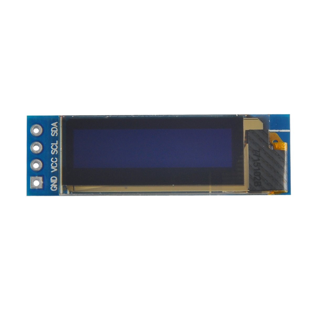
I principali componenti di questo progetto includono la scheda Arduino e il modulo display OLED SSD1306. Il display SSD1306 utilizza il protocollo di comunicazione I2C, che semplifica il cablaggio richiedendo solo due linee dati: SDA per i dati e SCL per il segnale di clock. Il display funziona a tensioni comprese tra 3.3V e 5V, rendendolo compatibile con la maggior parte delle schede Arduino.
Oltre al display, avrai bisogno di cavi jumper per collegare il modulo al tuo Arduino. I collegamenti includono VCC per l'alimentazione, GND per la massa, SDA al pin dati dell'Arduino e SCL al pin di clock. Questa configurazione consente una comunicazione semplice tra l'Arduino e il display OLED.
Dettagli della scheda tecnica
| Produttore | Adafruit |
|---|---|
| Numero di parte | SSD1306 |
| Tensione logica/IO | 3.3 V - 5 V |
| Tensione di alimentazione | 3.3 V - 5 V |
| Risoluzione del display | 128 x 64 pixel |
| Indirizzo I2C | 0x3C |
| Interfaccia | I2C |
| Pacchetto | Modulo |
- Assicurati che il cablaggio sia corretto: VCC a 3.3V o 5V, GND a massa, SDA su A4, SCL su A5 (per Arduino Uno).
- Il display richiede resistenze di pull-up sulle linee SDA e SCL se non sono già presenti.
- Verifica che l'indirizzo I2C sia impostato correttamente nel codice, solitamente 0x3C per questo display.
- Usa una libreria adatta come Adafruit_SSD1306 per una facile integrazione.
- Cancella il display prima di disegnare nuovi elementi grafici per evitare artefatti di sovrapposizione.
Istruzioni di cablaggio

Per collegare il display OLED SSD1306 al tuo Arduino, segui questi passaggi:
Collega il pin VCC del display OLED al pin 5V (o 3.3V) dell'Arduino. Successivamente, collega il pin GND del display al pin GND dell'Arduino. Per la comunicazione I2C, collega il pin SDA del display al pin A4 dell'Arduino e il pin SCL al pin A5. Questa configurazione permetterà all'Arduino di comunicare con il display OLED usando il protocollo I2C.
Assicurati che tutte le connessioni siano sicure e verifica di utilizzare la tensione corretta per il modello di display in tuo possesso. Se stai usando un modello diverso di Arduino, i pin SDA e SCL potrebbero variare (ad esempio, sull'Arduino Mega, SDA è sul pin 20 e SCL sul pin 21).
Esempi di codice e guida passo-passo
Nel codice inizializziamo il display e configuriamo i parametri come l'indirizzo I2C e le dimensioni. Un identificatore chiave èdisplay, che rappresenta l'istanza del display SSD1306. Ecco un frammento della funzione setup:
void setup() {
  Serial.begin(9600);
  display.begin(SSD1306_SWITCHCAPVCC, 0x3C);  // initialize with the I2C addr 0x3C
}
In questo frammento, ildisplay.beginLa funzione inizializza il display con l'indirizzo I2C specificato. È essenziale che l'indirizzo corrisponda a quello del tuo display per garantire una comunicazione corretta.
Successivamente, nella funzione loop, usiamo ildisplay.clearDisplay()metodo per cancellare lo schermo prima di disegnare nuovo contenuto. Possiamo impostare la dimensione e la posizione del testo usando ilsetTextSizeesetCursormetodi:
void loop() {
  display.clearDisplay();
  display.setTextSize(2);
  display.setCursor(2,1); // set cursor at top left corner
  display.println("Robojax"); // display text
}
Qui il testo "Robojax" viene visualizzato alle coordinate (2,1) sullo schermo. Questo permette un posizionamento preciso del testo sul display OLED.
Infine, per visualizzare le modifiche sul display, chiamiamodisplay.display(). Questa funzione invia tutti i comandi memorizzati nel buffer al display per aggiornare il suo contenuto:
display.display();Questa dovrebbe essere l'ultima riga della tua funzione loop per garantire che tutti i comandi di disegno vengano eseguiti. Se dimentichi questo passaggio, nulla verrà visualizzato sul display.
Ricorda: il codice completo si trova sotto l'articolo per tua consultazione.
Dimostrazione / Cosa aspettarsi
Dopo aver caricato il codice sul tuo Arduino, dovresti vedere il testo "Robojax" visualizzato sullo schermo OLED. Il codice dimostra anche lo scorrimento del testo e il disegno di linee, forme e altre grafiche sul display. Fai attenzione a eventuali errori comuni, come cablaggio errato o indirizzi I2C non corrispondenti, che possono impedire al display di funzionare correttamente (nel video a 10:00).
Marcatori temporali del video
- 00:00- Introduzione al display OLED SSD1306
- 02:30- Cablaggio del display
- 05:00- Revisione del codice
- 08:00- Dimostrazione delle funzionalità del display
- 10:00- Problemi comuni e risoluzione dei problemi
Immagini

/*
 * Original source: https://github.com/adafruit/Adafruit_SSD1306
 * This is the Arduino code for the SSD1306 OLED 128 x 64 Display.
 * Watch the video for details and demo: http://youtu.be/UmYiHTOz-5k
 * This code has been modified to print specific elements such as text, lines, circles, rectangles, etc.
 * I have added a custom method to make printing text easy.

 If you get the error: Adafruit_GFX.h not found, download the Adafruit-GFX Library from:
 https://github.com/adafruit/Adafruit-GFX-Library

 Purchase this OLED module from Amazon: https://amzn.to/36zFvTb

 *  *
 * Written by Ahmad Shamshiri for Robojax Video channel, www.Robojax.com
 * Date: December 17, 2017, in Ajax, Ontario, Canada
 * Permission granted to share this code, provided that this
 * note is kept with the code.
 * Disclaimer: This code is "AS IS" and for educational purposes only.
 * This code has been downloaded from https://robojax.com
 *
 */

/*********************************************************************
This is an example for our monochrome OLEDs based on SSD1306 drivers.

  Pick one up today in the Adafruit shop!
  ------> http://www.adafruit.com/category/63_98

This example is for a 128x64 size display using I2C to communicate.
3 pins are required to interface (2 I2C and one reset).

Adafruit invests time and resources providing this open source code,
please support Adafruit and open-source hardware by purchasing
products from Adafruit!

Written by Limor Fried/Ladyada for Adafruit Industries.
BSD license, check license.txt for more information.
All text above, and the splash screen must be included in any redistribution.
*********************************************************************/

#include <SPI.h>
#include <Wire.h>
#include <Adafruit_GFX.h>
#include <Adafruit_SSD1306.h>

#define OLED_RESET 4
Adafruit_SSD1306 display(OLED_RESET);

#define NUMFLAKES 10
#define XPOS 0
#define YPOS 1
#define DELTAY 2


#define LOGO16_GLCD_HEIGHT 16 // do not change this. Error in video
#define LOGO16_GLCD_WIDTH  16 // do not change this. Error in video
static const unsigned char PROGMEM logo16_glcd_bmp[] =
{ B00000000, B11000000,
  B00000001, B11000000,
  B00000001, B11000000,
  B00000011, B11100000,
  B11110011, B11100000,
  B11111110, B11111000,
  B01111110, B11111111,
  B00110011, B10011111,
  B00011111, B11111100,
  B00001101, B01110000,
  B00011011, B10100000,
  B00111111, B11100000,
  B00111111, B11110000,
  B01111100, B11110000,
  B01110000, B01110000,
  B00000000, B00110000 };

    // look at line 27 to 30 of Adafruit_SSD1306.h inside the library to select the dimensions
#if (SSD1306_LCDHEIGHT != 64)
#error("Height incorrect, please fix Adafruit_SSD1306.h!");
#endif

void setup()   {
  Serial.begin(9600);

  // by default, we'll generate the high voltage from the 3.3v line internally! (neat!)
  display.begin(SSD1306_SWITCHCAPVCC, 0x3C);  // initialize with the I2C addr 0x3D (for the 128x64)
  // init done

}


void loop() {
 display.clearDisplay();
  robojaxText("Values", 3, 0, 2, false);
  robojaxText("V: 41v", 3, 22, 2, false);
  robojaxText("Temperature: 32C", 4, 45, 1, true);
  display.drawLine(1, 37, 100, 37, WHITE);
  display.drawRect(1, 20, 100,40, WHITE);
  //display.drawCircle(63,31, 31, WHITE);
   //display.startscrollright(0x00, 0x0F);
  display.display();
   delay(20000);
}

/*
 * robojaxText(String text, int x, int y, int size, boolean d)
 * text is the text string to be printed.
 * x is the integer x position of the text.
 * y is the integer y position of the text.
 * size is the text size (1, 2, 3, etc.).
 * d is a boolean value (true or false).  Its purpose is unclear, use true.
 */
void robojaxText(String text, int x, int y,int size, boolean d) {

  display.setTextSize(size);
  display.setTextColor(WHITE);
  display.setCursor(x,y);
  display.println(text);
  if(d){
    display.display();
  }

  delay(100);
}/*
* Original source: https://github.com/adafruit/Adafruit_SSD1306
* This is the Arduino code for the SSD1306 OLED 128 x 64 Display
* watch the video for details and demo http://youtu.be/UmYiHTOz-5k
* This code has been modified to print specific elements such as text, lines, circles, rectangles, etc.
* *
* *
* Written by Ahmad Shamshiri for Robojax Video channel www.Robojax.com
* Date: December 15, 2017, in Ajax, Ontario, Canada
* Permission granted to share this code given that this
* note is kept with the code.
* Disclaimer: this code is "AS IS" and for educational purposes only.
* This code has been downloaded from https://robojax.com
*
*/
/*********************************************************************
This is an example for our Monochrome OLEDs based on SSD1306 drivers
Pick one up today in the Adafruit shop!
------> http://www.adafruit.com/category/63_98
This example is for a 128x64 size display using I2C to communicate.
3 pins are required to interface (2 I2C and one reset).
Adafruit invests time and resources providing this open source code,
please support Adafruit and open-source hardware by purchasing
products from Adafruit!
Written by Limor Fried/Ladyada for Adafruit Industries.
BSD license, check license.txt for more information
All text above, and the splash screen must be included in any redistribution
*********************************************************************/
#include <SPI.h>
#include <Wire.h>
#include <Adafruit_GFX.h>
#include <Adafruit_SSD1306.h>
#define OLED_RESET 4
Adafruit_SSD1306 display(OLED_RESET);
#define NUMFLAKES 10
#define XPOS 0
#define YPOS 1
#define DELTAY 2
#define LOGO16_GLCD_HEIGHT 16 // do not change this. Error in video
#define LOGO16_GLCD_WIDTH 16 // do not change this. Error in video
static const unsigned char PROGMEM logo16_glcd_bmp[] =
{ B00000000, B11000000,
B00000001, B11000000,
B00000001, B11000000,
B00000011, B11100000,
B11110011, B11100000,
B11111110, B11111000,
B01111110, B11111111,
B00110011, B10011111,
B00011111, B11111100,
B00001101, B01110000,
B00011011, B10100000,
B00111111, B11100000,
B00111111, B11110000,
B01111100, B11110000,
B01110000, B01110000,
B00000000, B00110000 };
// look at line 27 to 30 of Adafruit_SSD1306.h inside the library to select the dimensions
#if (SSD1306_LCDHEIGHT != 64)
#error("Height incorrect, please fix Adafruit_SSD1306.h!");
#endif
void setup() {
Serial.begin(9600);
// by default, we'll generate the high voltage from the 3.3v line internally! (neat!)
display.begin(SSD1306_SWITCHCAPVCC, 0x3C); // initialize with the I2C addr 0x3D (for the 128x64)
// init done
}
void loop() {
display.clearDisplay();
display.setTextSize(2);
display.setTextColor(WHITE);
display.setCursor(2,1);// set the cursor at x=2, y=1 which is top left corner of display
display.println("Robojax");// the actual text
display.setCursor(2,18);
display.println("YouTube");// set the cursor at x=2, y=18 which is top left under the first text line
display.drawLine(0,16, display.width()-1, 16, WHITE); // drawing from the point x=0, y=16 to x=64-1 y=16
display.display();
display.startscrollright(0x00, 0x0F);
delay(2000);
display.stopscroll();
delay(1000);
display.startscrollleft(0x00, 0x0F);
delay(2000);
display.stopscroll();
delay(1000);
display.startscrolldiagright(0x00, 0x07);
delay(2000);
display.startscrolldiagleft(0x00, 0x07);
delay(2000);
display.stopscroll();
delay(10000);
}/*********************************************************************
Original source: http://playground.arduino.cc/Main/I2cScanner
This program will find the I2C address on the I2C device. Just upload the code into your Arduino
and open the serial monitor and wait. It will display the I2C address as 0x3C or similar.
* Please view other RoboJax codes and videos at http://robojax.com/learn/arduino
* If you are sharing this code, you must keep this copyright note.
*
*********************************************************************/
#include <Wire.h>
void setup()
{
Wire.begin();
Serial.begin(9600);
while (!Serial); // Leonardo: wait for serial monitor
Serial.println("\nI2C Scanner");
}
void loop()
{
byte error, address;
int nDevices;
Serial.println("Scanning...");
nDevices = 0;
for(address = 1; address < 127; address++ )
{
// The i2c_scanner uses the return value of
// the Wire.endTransmission to see if
// a device did acknowledge the address.
Wire.beginTransmission(address);
error = Wire.endTransmission();
if (error == 0)
{
Serial.print("I2C device found at address 0x");
if (address<16)
Serial.print("0");
Serial.print(address,HEX);
Serial.println(" !");
nDevices++;
}
else if (error==4)
{
Serial.print("Unknown error at address 0x");
if (address<16)
Serial.print("0");
Serial.println(address,HEX);
}
}
if (nDevices == 0)
Serial.println("No I2C devices found\n");
else
Serial.println("done\n");
delay(5000); // wait 5 seconds for next scan
}Risorse e riferimenti
File📁
Nessun file disponibile.