Código y vídeo de Arduino para la pantalla OLED SSD1306 128 x 64
En este tutorial exploraremos cómo usar la pantalla OLED SSD1306 128 x 64 con un Arduino. El SSD1306 es una pantalla versátil que te permite mostrar texto, gráficos y diversas formas con facilidad. Al final de este artículo, podrás configurar la pantalla y ejecutar código que demuestre sus capacidades.

Le guiaremos a través de las conexiones de hardware necesarias y proporcionaremos fragmentos de código para ayudarle a comprender los identificadores clave utilizados en el programa. Para una explicación más visual, asegúrese de ver el video asociado (en el video a las 00:00).
Hardware explicado
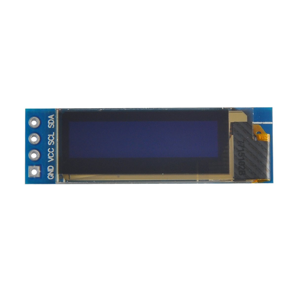
Los componentes principales de este proyecto incluyen la placa Arduino y el módulo de pantalla OLED SSD1306. La pantalla SSD1306 utiliza el protocolo de comunicación I2C, que simplifica el cableado al requerir solo dos líneas de datos: SDA para datos y SCL para la señal de reloj. La pantalla funciona a voltajes entre 3.3V y 5V, lo que la hace compatible con la mayoría de las placas Arduino.
Además de la pantalla, necesitarás cables de puente para conectar el módulo a tu Arduino. Las conexiones incluyen VCC para la alimentación, GND para tierra, SDA al pin de datos del Arduino y SCL al pin de reloj. Esta configuración permite una comunicación sencilla entre el Arduino y la pantalla OLED.
Detalles de la hoja de datos
| Fabricante | Adafruit |
|---|---|
| Número de pieza | SSD1306 |
| Voltaje lógico/E/S | 3.3 V - 5 V |
| Tensión de alimentación | 3.3 V - 5 V |
| Resolución de pantalla | 128 x 64 píxeles |
| dirección I2C | 0x3C |
| Interfaz | I2C |
| Paquete | Módulo |
- Asegúrese de que el cableado sea correcto: VCC a 3.3V o 5V, GND a tierra, SDA a A4, SCL a A5 (para Arduino Uno).
- La pantalla requiere resistencias de pull-up en las líneas SDA y SCL si no están ya incluidas.
- Verifique que la dirección I2C esté configurada correctamente en el código; típicamente 0x3C para esta pantalla.
- Utilice una biblioteca adecuada, como Adafruit_SSD1306, para una integración sencilla.
- Borre la pantalla antes de dibujar nuevos gráficos para evitar artefactos de superposición.
Instrucciones de cableado

Para cablear la pantalla OLED SSD1306 a tu Arduino, sigue estos pasos:
Conecta el pin VCC de la pantalla OLED al pin de 5V (o 3.3V) del Arduino. A continuación, conecta el pin GND de la pantalla al pin de tierra del Arduino. Para la comunicación I2C, conecta el pin SDA de la pantalla al pin A4 del Arduino y el pin SCL al pin A5. Esta configuración permitirá que el Arduino se comunique con la pantalla OLED usando el protocolo I2C.
Asegúrese de que todas las conexiones estén seguras y compruebe dos veces que está utilizando el voltaje correcto para su modelo de pantalla específico. Si está usando un modelo de Arduino diferente, los pines SDA y SCL pueden variar (p. ej., para Arduino Mega, SDA está en el pin 20 y SCL está en el pin 21).
Ejemplos de código y guía paso a paso
En el código, inicializamos la pantalla y configuramos parámetros como la dirección I2C y las dimensiones. Un identificador clave esdisplay, que representa la instancia de la pantalla SSD1306. Aquí hay un fragmento de la función setup:
void setup() {
  Serial.begin(9600);
  display.begin(SSD1306_SWITCHCAPVCC, 0x3C);  // initialize with the I2C addr 0x3C
}
En este fragmento, eldisplay.beginLa función inicializa la pantalla con la dirección I2C especificada. Es esencial que la dirección coincida con la de su pantalla para garantizar una comunicación adecuada.
A continuación, en la función loop, usamos eldisplay.clearDisplay()método para borrar la pantalla antes de dibujar contenido nuevo. Podemos establecer el tamaño y la posición del texto usando elsetTextSizeysetCursormétodos:
void loop() {
  display.clearDisplay();
  display.setTextSize(2);
  display.setCursor(2,1); // set cursor at top left corner
  display.println("Robojax"); // display text
}
Aquí, el texto "Robojax" se muestra en las coordenadas (2,1) de la pantalla. Esto permite colocar el texto de forma precisa en la pantalla OLED.
Finalmente, para renderizar los cambios en la pantalla, llamamosdisplay.display(). Esta función envía todos los comandos almacenados en el búfer a la pantalla para actualizar su contenido:
display.display();Esta debe ser la última línea de tu función loop para asegurarte de que todos los comandos de dibujo se ejecuten. Si olvidas este paso, no aparecerá nada en la pantalla.
Recuerde que el código completo se encuentra debajo del artículo para su consulta.
Demostración / Qué esperar
Después de subir el código a tu Arduino, deberías ver el texto "Robojax" en la pantalla OLED. El código también muestra cómo desplazar texto y dibujar líneas, formas y otros gráficos en la pantalla. Presta atención a posibles errores comunes, como un cableado incorrecto o direcciones I2C que no coinciden, que pueden impedir que la pantalla funcione correctamente (en el video a las 10:00).
Marcas de tiempo del vídeo
- 00:00- Introducción a la pantalla OLED SSD1306
- 02:30- Cableado de la pantalla
- 05:00- Recorrido por el código
- 08:00- Demostración de las funciones de la pantalla
- 10:00- Problemas comunes y solución de problemas
Imágenes

/*
 * Original source: https://github.com/adafruit/Adafruit_SSD1306
 * This is the Arduino code for the SSD1306 OLED 128 x 64 Display.
 * Watch the video for details and demo: http://youtu.be/UmYiHTOz-5k
 * This code has been modified to print specific elements such as text, lines, circles, rectangles, etc.
 * I have added a custom method to make printing text easy.

 If you get the error: Adafruit_GFX.h not found, download the Adafruit-GFX Library from:
 https://github.com/adafruit/Adafruit-GFX-Library

 Purchase this OLED module from Amazon: https://amzn.to/36zFvTb

 *  *
 * Written by Ahmad Shamshiri for Robojax Video channel, www.Robojax.com
 * Date: December 17, 2017, in Ajax, Ontario, Canada
 * Permission granted to share this code, provided that this
 * note is kept with the code.
 * Disclaimer: This code is "AS IS" and for educational purposes only.
 * This code has been downloaded from https://robojax.com
 *
 */

/*********************************************************************
This is an example for our monochrome OLEDs based on SSD1306 drivers.

  Pick one up today in the Adafruit shop!
  ------> http://www.adafruit.com/category/63_98

This example is for a 128x64 size display using I2C to communicate.
3 pins are required to interface (2 I2C and one reset).

Adafruit invests time and resources providing this open source code,
please support Adafruit and open-source hardware by purchasing
products from Adafruit!

Written by Limor Fried/Ladyada for Adafruit Industries.
BSD license, check license.txt for more information.
All text above, and the splash screen must be included in any redistribution.
*********************************************************************/

#include <SPI.h>
#include <Wire.h>
#include <Adafruit_GFX.h>
#include <Adafruit_SSD1306.h>

#define OLED_RESET 4
Adafruit_SSD1306 display(OLED_RESET);

#define NUMFLAKES 10
#define XPOS 0
#define YPOS 1
#define DELTAY 2


#define LOGO16_GLCD_HEIGHT 16 // do not change this. Error in video
#define LOGO16_GLCD_WIDTH  16 // do not change this. Error in video
static const unsigned char PROGMEM logo16_glcd_bmp[] =
{ B00000000, B11000000,
  B00000001, B11000000,
  B00000001, B11000000,
  B00000011, B11100000,
  B11110011, B11100000,
  B11111110, B11111000,
  B01111110, B11111111,
  B00110011, B10011111,
  B00011111, B11111100,
  B00001101, B01110000,
  B00011011, B10100000,
  B00111111, B11100000,
  B00111111, B11110000,
  B01111100, B11110000,
  B01110000, B01110000,
  B00000000, B00110000 };

    // look at line 27 to 30 of Adafruit_SSD1306.h inside the library to select the dimensions
#if (SSD1306_LCDHEIGHT != 64)
#error("Height incorrect, please fix Adafruit_SSD1306.h!");
#endif

void setup()   {
  Serial.begin(9600);

  // by default, we'll generate the high voltage from the 3.3v line internally! (neat!)
  display.begin(SSD1306_SWITCHCAPVCC, 0x3C);  // initialize with the I2C addr 0x3D (for the 128x64)
  // init done

}


void loop() {
 display.clearDisplay();
  robojaxText("Values", 3, 0, 2, false);
  robojaxText("V: 41v", 3, 22, 2, false);
  robojaxText("Temperature: 32C", 4, 45, 1, true);
  display.drawLine(1, 37, 100, 37, WHITE);
  display.drawRect(1, 20, 100,40, WHITE);
  //display.drawCircle(63,31, 31, WHITE);
   //display.startscrollright(0x00, 0x0F);
  display.display();
   delay(20000);
}

/*
 * robojaxText(String text, int x, int y, int size, boolean d)
 * text is the text string to be printed.
 * x is the integer x position of the text.
 * y is the integer y position of the text.
 * size is the text size (1, 2, 3, etc.).
 * d is a boolean value (true or false).  Its purpose is unclear, use true.
 */
void robojaxText(String text, int x, int y,int size, boolean d) {

  display.setTextSize(size);
  display.setTextColor(WHITE);
  display.setCursor(x,y);
  display.println(text);
  if(d){
    display.display();
  }

  delay(100);
}/*
* Original source: https://github.com/adafruit/Adafruit_SSD1306
* This is the Arduino code for the SSD1306 OLED 128 x 64 Display
* watch the video for details and demo http://youtu.be/UmYiHTOz-5k
* This code has been modified to print specific elements such as text, lines, circles, rectangles, etc.
* *
* *
* Written by Ahmad Shamshiri for Robojax Video channel www.Robojax.com
* Date: December 15, 2017, in Ajax, Ontario, Canada
* Permission granted to share this code given that this
* note is kept with the code.
* Disclaimer: this code is "AS IS" and for educational purposes only.
* This code has been downloaded from https://robojax.com
*
*/
/*********************************************************************
This is an example for our Monochrome OLEDs based on SSD1306 drivers
Pick one up today in the Adafruit shop!
------> http://www.adafruit.com/category/63_98
This example is for a 128x64 size display using I2C to communicate.
3 pins are required to interface (2 I2C and one reset).
Adafruit invests time and resources providing this open source code,
please support Adafruit and open-source hardware by purchasing
products from Adafruit!
Written by Limor Fried/Ladyada for Adafruit Industries.
BSD license, check license.txt for more information
All text above, and the splash screen must be included in any redistribution
*********************************************************************/
#include <SPI.h>
#include <Wire.h>
#include <Adafruit_GFX.h>
#include <Adafruit_SSD1306.h>
#define OLED_RESET 4
Adafruit_SSD1306 display(OLED_RESET);
#define NUMFLAKES 10
#define XPOS 0
#define YPOS 1
#define DELTAY 2
#define LOGO16_GLCD_HEIGHT 16 // do not change this. Error in video
#define LOGO16_GLCD_WIDTH 16 // do not change this. Error in video
static const unsigned char PROGMEM logo16_glcd_bmp[] =
{ B00000000, B11000000,
B00000001, B11000000,
B00000001, B11000000,
B00000011, B11100000,
B11110011, B11100000,
B11111110, B11111000,
B01111110, B11111111,
B00110011, B10011111,
B00011111, B11111100,
B00001101, B01110000,
B00011011, B10100000,
B00111111, B11100000,
B00111111, B11110000,
B01111100, B11110000,
B01110000, B01110000,
B00000000, B00110000 };
// look at line 27 to 30 of Adafruit_SSD1306.h inside the library to select the dimensions
#if (SSD1306_LCDHEIGHT != 64)
#error("Height incorrect, please fix Adafruit_SSD1306.h!");
#endif
void setup() {
Serial.begin(9600);
// by default, we'll generate the high voltage from the 3.3v line internally! (neat!)
display.begin(SSD1306_SWITCHCAPVCC, 0x3C); // initialize with the I2C addr 0x3D (for the 128x64)
// init done
}
void loop() {
display.clearDisplay();
display.setTextSize(2);
display.setTextColor(WHITE);
display.setCursor(2,1);// set the cursor at x=2, y=1 which is top left corner of display
display.println("Robojax");// the actual text
display.setCursor(2,18);
display.println("YouTube");// set the cursor at x=2, y=18 which is top left under the first text line
display.drawLine(0,16, display.width()-1, 16, WHITE); // drawing from the point x=0, y=16 to x=64-1 y=16
display.display();
display.startscrollright(0x00, 0x0F);
delay(2000);
display.stopscroll();
delay(1000);
display.startscrollleft(0x00, 0x0F);
delay(2000);
display.stopscroll();
delay(1000);
display.startscrolldiagright(0x00, 0x07);
delay(2000);
display.startscrolldiagleft(0x00, 0x07);
delay(2000);
display.stopscroll();
delay(10000);
}/*********************************************************************
Original source: http://playground.arduino.cc/Main/I2cScanner
This program will find the I2C address on the I2C device. Just upload the code into your Arduino
and open the serial monitor and wait. It will display the I2C address as 0x3C or similar.
* Please view other RoboJax codes and videos at http://robojax.com/learn/arduino
* If you are sharing this code, you must keep this copyright note.
*
*********************************************************************/
#include <Wire.h>
void setup()
{
Wire.begin();
Serial.begin(9600);
while (!Serial); // Leonardo: wait for serial monitor
Serial.println("\nI2C Scanner");
}
void loop()
{
byte error, address;
int nDevices;
Serial.println("Scanning...");
nDevices = 0;
for(address = 1; address < 127; address++ )
{
// The i2c_scanner uses the return value of
// the Wire.endTransmission to see if
// a device did acknowledge the address.
Wire.beginTransmission(address);
error = Wire.endTransmission();
if (error == 0)
{
Serial.print("I2C device found at address 0x");
if (address<16)
Serial.print("0");
Serial.print(address,HEX);
Serial.println(" !");
nDevices++;
}
else if (error==4)
{
Serial.print("Unknown error at address 0x");
if (address<16)
Serial.print("0");
Serial.println(address,HEX);
}
}
if (nDevices == 0)
Serial.println("No I2C devices found\n");
else
Serial.println("done\n");
delay(5000); // wait 5 seconds for next scan
}Recursos y referencias
Archivos📁
No hay archivos disponibles.