Arduino-Code und Video für SSD1306 OLED 128 x 64 Display
In diesem Tutorial werden wir untersuchen, wie man das SSD1306 OLED 128 x 64 Display mit einem Arduino verwendet. Der SSD1306 ist ein vielseitiges Display, mit dem Sie einfach Text, Grafiken und verschiedene Formen anzeigen können. Am Ende dieses Artikels werden Sie in der Lage sein, das Display einzurichten und Code auszuführen, der seine Fähigkeiten demonstriert.

Wir führen Sie durch die notwendigen Hardwareverbindungen und stellen Codebeispiele bereit, damit Sie die wichtigsten im Programm verwendeten Bezeichner verstehen. Für eine anschaulichere Erklärung sollten Sie unbedingt das zugehörige Video ansehen (im Video bei 00:00).
Hardware erklärt
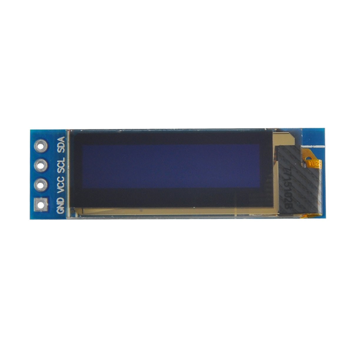
Die Hauptkomponenten dieses Projekts sind das Arduino-Board und das SSD1306-OLED-Displaymodul. Das SSD1306-Display nutzt das I2C-Kommunikationsprotokoll, das die Verkabelung vereinfacht, da nur zwei Leitungen benötigt werden: SDA für Daten und SCL für das Taktsignal. Das Display arbeitet bei Spannungen zwischen 3,3 V und 5 V und ist damit mit den meisten Arduino-Boards kompatibel.
Zusätzlich zum Display benötigen Sie Jumperkabel, um das Modul mit Ihrem Arduino zu verbinden. Die Anschlüsse umfassen VCC für die Stromversorgung, GND für Masse, SDA für den Datenpin des Arduino und SCL für den Taktpin. Diese Konfiguration ermöglicht eine einfache Kommunikation zwischen dem Arduino und dem OLED-Display.
Details zum Datenblatt
| Hersteller | Adafruit |
|---|---|
| Teilenummer | SSD1306 |
| Logik-/E/A-Spannung | 3.3 V - 5 V |
| Versorgungsspannung | 3.3 V - 5 V |
| Bildschirmauflösung | 128 x 64 Pixel |
| I2C-Adresse | 0x3C |
| Schnittstelle | I2C |
| Paket | Modul |
- Stellen Sie die korrekte Verdrahtung sicher: VCC an 3.3V oder 5V, GND an Masse, SDA an A4, SCL an A5 (für Arduino Uno).
- Das Display benötigt Pull-up-Widerstände an den SDA- und SCL-Leitungen, falls diese nicht bereits vorhanden sind.
- Überprüfen Sie, ob die I2C‑Adresse im Code korrekt gesetzt ist, typischerweise 0x3C für dieses Display.
- Verwenden Sie eine geeignete Bibliothek wie Adafruit_SSD1306, um die Integration zu erleichtern.
- Löschen Sie das Display, bevor Sie neue Grafiken zeichnen, um überlappende Artefakte zu vermeiden.
Verdrahtungsanleitung

Um das SSD1306-OLED-Display an Ihren Arduino anzuschließen, befolgen Sie diese Schritte:
Verbinden Sie den VCC-Pin des OLED-Displays mit dem 5V- (oder 3,3V-)Pin am Arduino. Verbinden Sie als Nächstes den GND-Pin des Displays mit dem Masse-Pin am Arduino. Für die I2C-Kommunikation verbinden Sie den SDA-Pin des Displays mit dem A4-Pin am Arduino und den SCL-Pin mit dem A5-Pin. Diese Konfiguration ermöglicht dem Arduino die Kommunikation mit dem OLED-Display über das I2C-Protokoll.
Stellen Sie sicher, dass alle Verbindungen fest sitzen, und überprüfen Sie nochmals, dass Sie die richtige Spannung für Ihr spezifisches Displaymodell verwenden. Wenn Sie ein anderes Arduino-Modell verwenden, können die SDA- und SCL-Pins variieren (z. B. beim Arduino Mega ist SDA auf Pin 20 und SCL auf Pin 21).
Code-Beispiele und Schritt-für-Schritt-Anleitung
Im Code initialisieren wir das Display und legen Parameter wie die I2C-Adresse und die Abmessungen fest. Ein wichtiger Bezeichner istdisplay, das die Instanz des SSD1306-Displays darstellt. Hier ist ein Ausschnitt aus der Setup-Funktion:
void setup() {
  Serial.begin(9600);
  display.begin(SSD1306_SWITCHCAPVCC, 0x3C);  // initialize with the I2C addr 0x3C
}
In diesem Snippet, dasdisplay.beginDie Funktion initialisiert das Display mit der angegebenen I2C-Adresse. Es ist wichtig, die Adresse mit Ihrem Display abzugleichen, um eine ordnungsgemäße Kommunikation zu gewährleisten.
Als Nächstes verwenden wir in der Loop-Funktion dasdisplay.clearDisplay()Methode, um den Bildschirm zu löschen, bevor neue Inhalte gezeichnet werden. Wir können die Textgröße und Position mit demsetTextSizeundsetCursorMethoden:
void loop() {
  display.clearDisplay();
  display.setTextSize(2);
  display.setCursor(2,1); // set cursor at top left corner
  display.println("Robojax"); // display text
}
Hier wird der Text "Robojax" an den Koordinaten (2,1) auf dem Bildschirm angezeigt. Dies ermöglicht eine präzise Platzierung von Text auf dem OLED-Display.
Um die Änderungen auf dem Display darzustellen, rufen wir schließlichdisplay.display(). Diese Funktion sendet alle gepufferten Befehle an das Display, um dessen Inhalt zu aktualisieren:
display.display();Dies sollte die letzte Zeile in Ihrer loop()-Funktion sein, um sicherzustellen, dass alle Zeichenbefehle ausgeführt werden. Wenn Sie diesen Schritt vergessen, wird nichts auf dem Display angezeigt.
Denken Sie daran, der vollständige Code befindet sich unter dem Artikel zu Ihrer Information.
Demonstration / Was Sie erwartet
Nach dem Hochladen des Codes auf Ihren Arduino sollten Sie den Text "Robojax" auf dem OLED-Bildschirm sehen. Der Code zeigt außerdem das Scrollen von Text und das Zeichnen von Linien, Formen und anderen Grafiken auf dem Display. Achten Sie auf häufige Stolperfallen, wie fehlerhafte Verkabelung oder falsche I2C-Adressen, die verhindern können, dass das Display korrekt funktioniert (im Video bei 10:00).
Video-Zeitstempel
- 00:00Einführung in das SSD1306-OLED-Display
- 02:30- Verdrahtung des Displays
- 05:00- Code-Durchgang
- 08:00- Demonstration der Displayfunktionen
- 10:00- Häufige Probleme und Fehlerbehebung
Bilder

/*
 * Original source: https://github.com/adafruit/Adafruit_SSD1306
 * This is the Arduino code for the SSD1306 OLED 128 x 64 Display.
 * Watch the video for details and demo: http://youtu.be/UmYiHTOz-5k
 * This code has been modified to print specific elements such as text, lines, circles, rectangles, etc.
 * I have added a custom method to make printing text easy.

 If you get the error: Adafruit_GFX.h not found, download the Adafruit-GFX Library from:
 https://github.com/adafruit/Adafruit-GFX-Library

 Purchase this OLED module from Amazon: https://amzn.to/36zFvTb

 *  *
 * Written by Ahmad Shamshiri for Robojax Video channel, www.Robojax.com
 * Date: December 17, 2017, in Ajax, Ontario, Canada
 * Permission granted to share this code, provided that this
 * note is kept with the code.
 * Disclaimer: This code is "AS IS" and for educational purposes only.
 * This code has been downloaded from https://robojax.com
 *
 */

/*********************************************************************
This is an example for our monochrome OLEDs based on SSD1306 drivers.

  Pick one up today in the Adafruit shop!
  ------> http://www.adafruit.com/category/63_98

This example is for a 128x64 size display using I2C to communicate.
3 pins are required to interface (2 I2C and one reset).

Adafruit invests time and resources providing this open source code,
please support Adafruit and open-source hardware by purchasing
products from Adafruit!

Written by Limor Fried/Ladyada for Adafruit Industries.
BSD license, check license.txt for more information.
All text above, and the splash screen must be included in any redistribution.
*********************************************************************/

#include <SPI.h>
#include <Wire.h>
#include <Adafruit_GFX.h>
#include <Adafruit_SSD1306.h>

#define OLED_RESET 4
Adafruit_SSD1306 display(OLED_RESET);

#define NUMFLAKES 10
#define XPOS 0
#define YPOS 1
#define DELTAY 2


#define LOGO16_GLCD_HEIGHT 16 // do not change this. Error in video
#define LOGO16_GLCD_WIDTH  16 // do not change this. Error in video
static const unsigned char PROGMEM logo16_glcd_bmp[] =
{ B00000000, B11000000,
  B00000001, B11000000,
  B00000001, B11000000,
  B00000011, B11100000,
  B11110011, B11100000,
  B11111110, B11111000,
  B01111110, B11111111,
  B00110011, B10011111,
  B00011111, B11111100,
  B00001101, B01110000,
  B00011011, B10100000,
  B00111111, B11100000,
  B00111111, B11110000,
  B01111100, B11110000,
  B01110000, B01110000,
  B00000000, B00110000 };

    // look at line 27 to 30 of Adafruit_SSD1306.h inside the library to select the dimensions
#if (SSD1306_LCDHEIGHT != 64)
#error("Height incorrect, please fix Adafruit_SSD1306.h!");
#endif

void setup()   {
  Serial.begin(9600);

  // by default, we'll generate the high voltage from the 3.3v line internally! (neat!)
  display.begin(SSD1306_SWITCHCAPVCC, 0x3C);  // initialize with the I2C addr 0x3D (for the 128x64)
  // init done

}


void loop() {
 display.clearDisplay();
  robojaxText("Values", 3, 0, 2, false);
  robojaxText("V: 41v", 3, 22, 2, false);
  robojaxText("Temperature: 32C", 4, 45, 1, true);
  display.drawLine(1, 37, 100, 37, WHITE);
  display.drawRect(1, 20, 100,40, WHITE);
  //display.drawCircle(63,31, 31, WHITE);
   //display.startscrollright(0x00, 0x0F);
  display.display();
   delay(20000);
}

/*
 * robojaxText(String text, int x, int y, int size, boolean d)
 * text is the text string to be printed.
 * x is the integer x position of the text.
 * y is the integer y position of the text.
 * size is the text size (1, 2, 3, etc.).
 * d is a boolean value (true or false).  Its purpose is unclear, use true.
 */
void robojaxText(String text, int x, int y,int size, boolean d) {

  display.setTextSize(size);
  display.setTextColor(WHITE);
  display.setCursor(x,y);
  display.println(text);
  if(d){
    display.display();
  }

  delay(100);
}/*
* Original source: https://github.com/adafruit/Adafruit_SSD1306
* This is the Arduino code for the SSD1306 OLED 128 x 64 Display
* watch the video for details and demo http://youtu.be/UmYiHTOz-5k
* This code has been modified to print specific elements such as text, lines, circles, rectangles, etc.
* *
* *
* Written by Ahmad Shamshiri for Robojax Video channel www.Robojax.com
* Date: December 15, 2017, in Ajax, Ontario, Canada
* Permission granted to share this code given that this
* note is kept with the code.
* Disclaimer: this code is "AS IS" and for educational purposes only.
* This code has been downloaded from https://robojax.com
*
*/
/*********************************************************************
This is an example for our Monochrome OLEDs based on SSD1306 drivers
Pick one up today in the Adafruit shop!
------> http://www.adafruit.com/category/63_98
This example is for a 128x64 size display using I2C to communicate.
3 pins are required to interface (2 I2C and one reset).
Adafruit invests time and resources providing this open source code,
please support Adafruit and open-source hardware by purchasing
products from Adafruit!
Written by Limor Fried/Ladyada for Adafruit Industries.
BSD license, check license.txt for more information
All text above, and the splash screen must be included in any redistribution
*********************************************************************/
#include <SPI.h>
#include <Wire.h>
#include <Adafruit_GFX.h>
#include <Adafruit_SSD1306.h>
#define OLED_RESET 4
Adafruit_SSD1306 display(OLED_RESET);
#define NUMFLAKES 10
#define XPOS 0
#define YPOS 1
#define DELTAY 2
#define LOGO16_GLCD_HEIGHT 16 // do not change this. Error in video
#define LOGO16_GLCD_WIDTH 16 // do not change this. Error in video
static const unsigned char PROGMEM logo16_glcd_bmp[] =
{ B00000000, B11000000,
B00000001, B11000000,
B00000001, B11000000,
B00000011, B11100000,
B11110011, B11100000,
B11111110, B11111000,
B01111110, B11111111,
B00110011, B10011111,
B00011111, B11111100,
B00001101, B01110000,
B00011011, B10100000,
B00111111, B11100000,
B00111111, B11110000,
B01111100, B11110000,
B01110000, B01110000,
B00000000, B00110000 };
// look at line 27 to 30 of Adafruit_SSD1306.h inside the library to select the dimensions
#if (SSD1306_LCDHEIGHT != 64)
#error("Height incorrect, please fix Adafruit_SSD1306.h!");
#endif
void setup() {
Serial.begin(9600);
// by default, we'll generate the high voltage from the 3.3v line internally! (neat!)
display.begin(SSD1306_SWITCHCAPVCC, 0x3C); // initialize with the I2C addr 0x3D (for the 128x64)
// init done
}
void loop() {
display.clearDisplay();
display.setTextSize(2);
display.setTextColor(WHITE);
display.setCursor(2,1);// set the cursor at x=2, y=1 which is top left corner of display
display.println("Robojax");// the actual text
display.setCursor(2,18);
display.println("YouTube");// set the cursor at x=2, y=18 which is top left under the first text line
display.drawLine(0,16, display.width()-1, 16, WHITE); // drawing from the point x=0, y=16 to x=64-1 y=16
display.display();
display.startscrollright(0x00, 0x0F);
delay(2000);
display.stopscroll();
delay(1000);
display.startscrollleft(0x00, 0x0F);
delay(2000);
display.stopscroll();
delay(1000);
display.startscrolldiagright(0x00, 0x07);
delay(2000);
display.startscrolldiagleft(0x00, 0x07);
delay(2000);
display.stopscroll();
delay(10000);
}/*********************************************************************
Original source: http://playground.arduino.cc/Main/I2cScanner
This program will find the I2C address on the I2C device. Just upload the code into your Arduino
and open the serial monitor and wait. It will display the I2C address as 0x3C or similar.
* Please view other RoboJax codes and videos at http://robojax.com/learn/arduino
* If you are sharing this code, you must keep this copyright note.
*
*********************************************************************/
#include <Wire.h>
void setup()
{
Wire.begin();
Serial.begin(9600);
while (!Serial); // Leonardo: wait for serial monitor
Serial.println("\nI2C Scanner");
}
void loop()
{
byte error, address;
int nDevices;
Serial.println("Scanning...");
nDevices = 0;
for(address = 1; address < 127; address++ )
{
// The i2c_scanner uses the return value of
// the Wire.endTransmission to see if
// a device did acknowledge the address.
Wire.beginTransmission(address);
error = Wire.endTransmission();
if (error == 0)
{
Serial.print("I2C device found at address 0x");
if (address<16)
Serial.print("0");
Serial.print(address,HEX);
Serial.println(" !");
nDevices++;
}
else if (error==4)
{
Serial.print("Unknown error at address 0x");
if (address<16)
Serial.print("0");
Serial.println(address,HEX);
}
}
if (nDevices == 0)
Serial.println("No I2C devices found\n");
else
Serial.println("done\n");
delay(5000); // wait 5 seconds for next scan
}Ressourcen & Referenzen
Dateien📁
Keine Dateien verfügbar.