This tutorial is part of: Controlling 16 or 32 Servo motor with PCA9685
These collection of tutorial with video help you control 32 or more servo motors using Arduino UNO, Nano, Mini or ESP32 . All codes provided

Controlling a 32 Servo Motor Using a PCA9685 Module and an ESP32 V4
In this tutorial, you will learn how to control up to 32 servo motors using an ESP32 microcontroller connected to a PCA9685 module. This is particularly useful for projects that require multiple servo motors to operate simultaneously without the use of Wi-Fi. The outcome will be a fully functional setup where you can manipulate the position of each servo motor individually.

This tutorial will guide you through the necessary hardware components, wiring instructions, and an overview of the code required to achieve this control. For a detailed demonstration, consider watching the associated video at (in video at 00:00).
Hardware Explained
The primary components used in this project are the ESP32 microcontroller and the PCA9685 PWM driver module. The ESP32 serves as the main controller that sends signals to the PCA9685 module, which in turn controls the servo motors. The PCA9685 can handle up to 16 servo motors per module, allowing for the connection of two modules to control a total of 32 servos.
The PCA9685 module operates using I2C communication, meaning it has two main wires for data transfer: SDA (data line) and SCL (clock line). It also requires a power supply to operate the servos, typically at 5V. The ESP32 acts as the master device, providing the necessary control signals to the slave PCA9685 modules.
Datasheet Details
| Manufacturer | Adafruit |
|---|---|
| Part number | PCA9685 |
| Logic/IO voltage | 3.3 V to 5.5 V |
| Supply voltage | 5 V |
| Output current (per channel) | ~20 mA |
| Peak current (per channel) | ~25 mA |
| PWM frequency guidance | 60 Hz |
| Input logic thresholds | 0.3*VDD (low), 0.7*VDD (high) |
| Voltage drop / RDS(on) / saturation | 0.5 V max |
| Thermal limits | 125 °C |
| Package | HTSSOP-28 |
| Notes / variants | 16 channel PWM controller |
- Use external power supply for servos (5V, 2A recommended).
- Ensure proper grounding between ESP32 and PCA9685.
- Check PWM frequency settings for optimal servo performance.
- Adjust pulse width limits based on servo specifications.
- Be cautious of current draw when multiple servos are active.
Wiring Instructions

To wire the PCA9685 to the ESP32, start by connecting the power and ground. Connect the VCC pin on the PCA9685 to a 5V power source, and connect the GND pin to one of the GND pins on the ESP32. This ensures both the module and the ESP32 share a common ground.
Next, for the I2C communication, connect the SDA pin on the PCA9685 to GPIO 21 on the ESP32 and the SCL pin to GPIO 22. This setup allows the ESP32 to communicate with the PCA9685 module properly. Make sure to use short wires to avoid noise in the communication lines, especially if you're working with multiple servos.
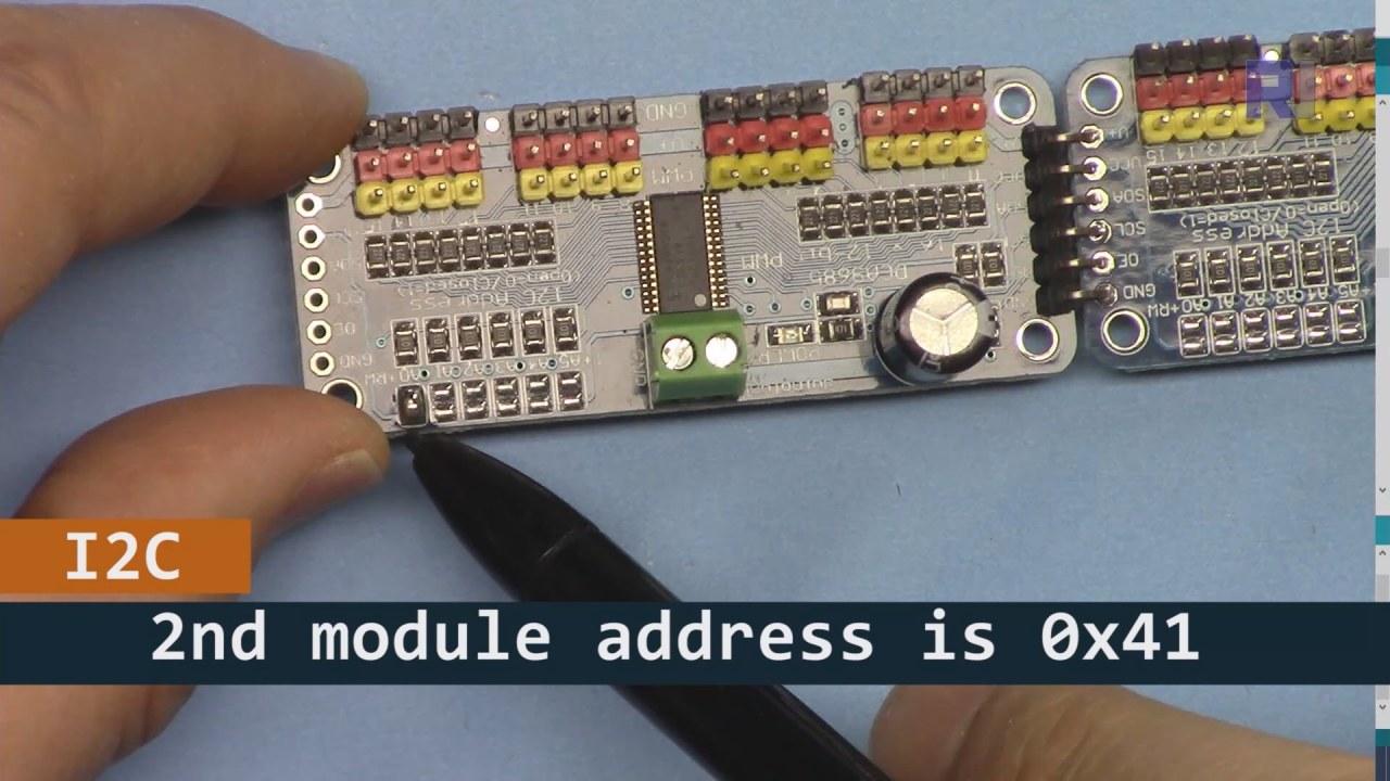
As shown in the image bove, for PCA9685 board 2 (on the left), make sure to solder that path to set I2C address so it is different from board 1 (on the righ).
Code Examples & Walkthrough
The code initializes the PCA9685 modules and sets the PWM frequency. The key identifiers in the code include board1 and board2, which represent the two PCA9685 modules connected to the ESP32. The setup() function initializes the serial monitor and sets the PWM frequency for both boards.
void setup() {
  Serial.begin(9600);
  Serial.println("32 channel Servo test!");

  board1.begin();
  board2.begin();
  board1.setPWMFreq(60);  // Analog servos run at ~60 Hz updates
  board2.setPWMFreq(60);
}
This excerpt shows the setup process, where the serial communication is initialized, and the PWM frequency is set for the servo drivers. The setPWMFreq(60) function ensures that the servos receive the correct frequency for smooth operation.
In the loop, a for loop iterates through angles from 0 to 180 degrees, sending pulse width commands to the servos connected to both PCA9685 boards. The function angleToPulse converts the angle to the corresponding pulse width.
void loop() {
    for(int angle = 0; angle < 181; angle += 10) {
        for(int i = 0; i < 16; i++) {
            board2.setPWM(i, 0, angleToPulse(angle));
            board1.setPWM(i, 0, angleToPulse(angle));
        }
    }
    delay(100);
}
This code excerpt demonstrates how the servos are controlled in a loop. The servo angle increments by 10 degrees, and the setPWM function is called for both boards to move the servos to the specified angle. The delay allows for a brief pause between movements.
Demonstration / What to Expect
Upon completing the wiring and uploading the code, you should see the servos moving in increments from 0 to 180 degrees. This will happen for all 32 servos connected to the two PCA9685 modules simultaneously. If any servo does not respond, check the power supply and ensure all connections are secure (in video at 12:30).

Video Timestamps
- 00:00 Start
- 00:36 Introduction
- 04:01 Wiring Explained (ESP32 only)
- 06:26 Preparing Arduino IDE for ESP32
- 08:34 Code Explained
- 13:40 Demonstration of running 32 Servo Motors
Images


This tutorial is part of: Controlling 16 or 32 Servo motor with PCA9685
- Arduino Code and Video for PCA9685 16-Channel 12-Bit Servo Controller V1
- Control 16 Servo Motors Using a PCA9685 Module and Arduino V2 Sketch #1: One-by-One
- Controlling 16 Servo Motors Using a PCA9685 Module and Arduino V2 Sketch: Individual Servo Control
- Controlling 16 Servo Motors Using a PCA9685 Module and Arduino V2 Sketch #3: All Servos Together
- Controlling a 32 Servo Motor Using a PCA9685 Module and Arduino V3 Sketch #1: All Servos Together
- Control 32 Servos over Wi-Fi Using ESP32 and PCA9685 via Desktop or Mobile Phone V5
/*
 * Original library source: https://github.com/adafruit/Adafruit-PWM-Servo-Driver-Library
 *
 * This is the Arduino code PCA6985 16 channel servo controller
 * to control 32 Servo Motors with ESP32 board without WiFi

  get this code and wiring from for this video:  http://robojax.com/RJT268
 *
 * This is V4 Video on PCA9685: https://youtu.be/JFdXB8Za5Os
 *
 * watch the video for details (V1) and demo http://youtu.be/y8X9X10Tn1k

 *

 * Written/updated by Ahmad Shamshiri for Robojax Video channel www.Robojax.com
 * Date: Dec 15, 2019, in Ajax, Ontario, Canada

 * Disclaimer: this code is "AS IS" and for educational purpose only.


or make donation using PayPal http://robojax.com/L/?id=64

 *  * This code is "AS IS" without warranty or liability. Free to be used as long as you keep this note intact.*
 * This code has been download from Robojax.com
    This program is free software: you can redistribute it and/or modify
    it under the terms of the GNU General Public License as published by
    the Free Software Foundation, either version 3 of the License, or
    (at your option) any later version.

    This program is distributed in the hope that it will be useful,
    but WITHOUT ANY WARRANTY; without even the implied warranty of
    MERCHANTABILITY or FITNESS FOR A PARTICULAR PURPOSE.  See the
    GNU General Public License for more details.

    You should have received a copy of the GNU General Public License
    along with this program.  If not, see <https://www.gnu.org/licenses/>.
 */
#include <Wire.h>

#include <Adafruit_PWMServoDriver.h>

// called this way, it uses the default address 0x40
Adafruit_PWMServoDriver board1 = Adafruit_PWMServoDriver(0x40);
Adafruit_PWMServoDriver board2 = Adafruit_PWMServoDriver(0x41);

// Depending on your servo make, the pulse width min and max may vary, you
// want these to be as small/large as possible without hitting the hard stop
// for max range. You'll have to tweak them as necessary to match the servos you
// have!
// Watch video V1 to understand the two lines below: http://youtu.be/y8X9X10Tn1k
#define SERVOMIN  125 // this is the 'minimum' pulse length count (out of 4096)
#define SERVOMAX  575 // this is the 'maximum' pulse length count (out of 4096)


int servoNumber = 0;

void setup() {
  Serial.begin(9600);
  Serial.println("32 channel Servo test!");

  board1.begin();
  board2.begin();
  board1.setPWMFreq(60);  // Analog servos run at ~60 Hz updates
  board2.setPWMFreq(60);
  //yield();
}

// the code inside loop() has been updated by Robojax
void loop() {


    for( int angle =0; angle<181; angle +=10){
      for(int i=0; i<16; i++)
        {
            board2.setPWM(i, 0, angleToPulse(angle) );
            board1.setPWM(i, 0, angleToPulse(angle) );
        }
    }

// robojax PCA9865 16 channel Servo control
  delay(100);

}

/*
 * angleToPulse(int ang)
 * gets angle in degree and returns the pulse width
 * also prints the value on seial monitor
 * written by Ahmad Shamshiri for Robojax, Robojax.com
 */
int angleToPulse(int ang){
   int pulse = map(ang,0, 180, SERVOMIN,SERVOMAX);// map angle of 0 to 180 to Servo min and Servo max
   Serial.print("Angle: ");Serial.print(ang);
   Serial.print(" pulse: ");Serial.println(pulse);
   return pulse;
}
Things you might need
-
AmazonPurchase PCA9685 from Amazonamzn.to
-
eBayPurchase PCA9685 from eBayebay.us
-
AliExpressPurchase PCA9685 from AliExpresss.click.aliexpress.com
-
BanggoodPurchase PCA9685 from Bangoodbanggood.com
Resources & references
No resources yet.
Files📁
Arduino Libraries (zip)
-
Adafruit-PWM-Servo-Driver-Library-master
Adafruit-PWM-Servo-Driver-Library-master.zip0.02 MB