How to Use an AC 80-260V 100A PZEM-061 Active Power Meter
In this tutorial, we will explore how to effectively use the PZEM-061 Active Power Meter, which is designed to measure both active and reactive power in AC circuits. This device operates within a voltage range of 80 to 260V and is capable of handling up to 100A, making it suitable for various applications globally. By the end of this tutorial, you will understand how to set up the meter, connect it to different devices, and interpret the readings accurately.

We will also investigate the effects of reactive power by connecting a capacitor in parallel with a load and observing how it influences the readings on the meter. This tutorial aims to provide a clear understanding of the device's capabilities and how to utilize it effectively for measuring power consumption. For a visual guide, be sure to check out the video accompanying this tutorial (in video at 00:00).
Hardware Explained
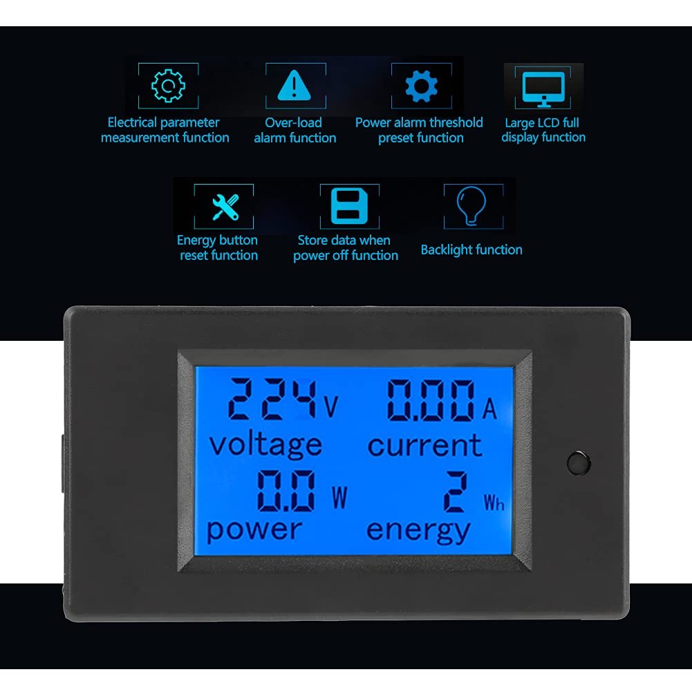
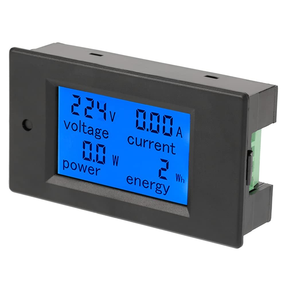
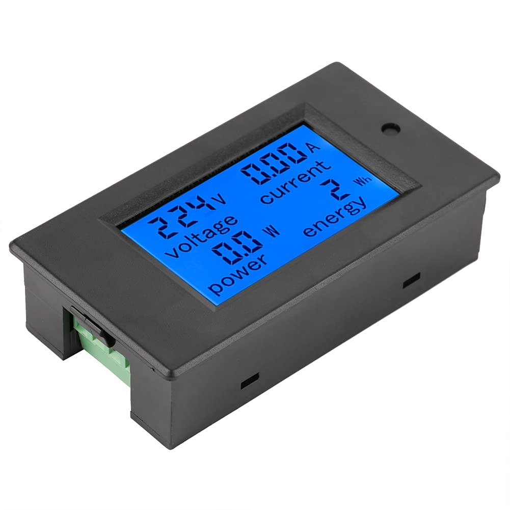
The PZEM-061 Active Power Meter is equipped with a current transformer (CT) that measures the current flowing through the wires. This transformer generates a magnetic field proportional to the current, allowing the device to derive the power readings accurately. The meter also has a display that shows real-time measurements of voltage, current, power, and energy consumed.
To operate the PZEM-061, you need to connect it to a suitable AC source. The device is straightforward to wire, requiring only a few connections. It features a backlit display for visibility in low-light conditions and has alarm capabilities for monitoring power thresholds.
Datasheet Details
| Manufacturer | PZEM |
|---|---|
| Part number | PZEM-061 |
| Logic/IO voltage | AC 80-260V |
| Rated current | 100A |
| Rated power | 22 kW |
| Frequency range | 45-65 Hz |
| Accuracy | 1% (typ.) |
| Display | LCD with backlight |
| Dimensions | 89.4mm x 49.5mm x 44.4mm |
| Notes / variants | Various models available |
- Ensure the current transformer is correctly positioned around the wire to measure current accurately.
- Use appropriate wire gauge to avoid voltage drops and overheating.
- Check the device's power rating to avoid exceeding the maximum load.
- Be cautious when working with AC voltage; ensure all connections are secure.
- Use a fuse for safety to protect against short circuits.
- Calibrate the device periodically to maintain accuracy.
- Pay attention to the frequency of your AC source for accurate readings.
-
PZEM-061-3
Wiring Instructions
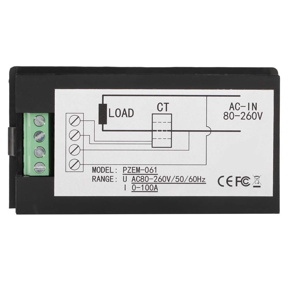
To wire the PZEM-061 Active Power Meter, start by connecting the current transformer (CT) to the meter. The CT has two wires that need to be soldered or connected to the meter's designated input. Ensure that the CT is placed around the live wire of the AC circuit where you want to measure current.
Next, connect the power supply to the meter using the provided JST connectors. The voltage input pins are typically labeled, so connect the live wire to the voltage input pin and the neutral wire to the corresponding neutral pin. Be mindful of the connections to avoid any reverse wiring, which could damage the device. Once everything is connected, plug the meter into an AC outlet to power it on.

Demonstration / What to Expect
When using the PZEM-061, you can expect to see immediate readings of voltage, current, and power consumption on the display. As you connect different devices, such as a toaster or a heat gun, the meter will accurately reflect their power usage, which is useful for monitoring energy consumption. Be aware that when no load is connected, the meter may still show a small value due to standby power.
During the demonstration, you will see how the meter responds to different loads. For example, when a toaster rated at 800W is turned on, the meter should show a reading close to that value, confirming its accuracy (in video at 10:00). If a capacitor is connected, you may notice variations in the readings, particularly in reactive power scenarios.
Video Timestamps
- 00:00 Introduction
- 04:54 Wiring Explained
- 07:05 Demonstration of power measurement
- 13:17 setting and Power Alarm
Images
Things you might need
-
eBay3.5mm bullet connectorsebay.us
-
eBayHereebay.ca
-
eBayJST connector on eBayebay.us
-
AliExpressPZEM-061 on AliExpresss.click.aliexpress.com
-
BanggoodPZEM-061 on Banggoodbanggood.com
Resources & references
-
External3.5mm bullet connectorsebay.us
-
ExternalHereebay.ca
-
ExternalJST connector on eBayebay.us
-
ExternalPZEM-061 on AliExpresss.click.aliexpress.com
-
ExternalPZEM-061 on Amazonamzn.to
-
ExternalPZEM-061 on Banggoodbanggood.com
Files📁
Datasheet (pdf)
-
AC digital power meter PZEM-061 manual
robojax_PZEM-061_power_meter_manual.pdf0.63 MB
User’s Manual
-
AC digital power meter PZEM-061 manual
robojax_PZEM-061_power_meter_manual.pdf0.63 MB