本教程是的一部分: 使用 PCA9685 控制 16 或 32 伺服电机
这套包含视频教程的合集将帮助您使用 Arduino UNO、Nano、Mini 或 ESP32 控制 32 个或更多伺服电机。所有代码均已提供。

使用PCA9685模块和Arduino V3控制32个伺服电机草图#1:所有伺服电机一起运行
在本教程中,我们将学习如何通过连接到Arduino的两个PCA9685 PWM驱动模块控制32个伺服电机。PCA9685是一个多功能模块,允许通过I2C通信轻松控制多个伺服电机。在本项目结束时,您将能够通过简单的设置使所有32个伺服电机协调运动。

我们还将实现一个按钮,可以同时开启或关闭所有伺服电机。这个功能增加了一层额外的控制,使项目更加互动。为了直观理解设置和代码,请务必查看伴随的视频(视频在00:00处)。
硬件解析
本项目的关键组件是PCA9685模块,它提供16个PWM信号通道。该模块使用I2C通信,SDA和SCL引脚负责数据传输。每个PCA9685可以控制最多16个舵机,但通过级联两个模块,我们可以同时控制32个舵机。
Arduino作为控制器,向PCA9685模块发送命令。每个伺服电机将连接到PCA9685的一个输出引脚,从而实现对其位置的精确控制。适当的外部电源供应至关重要,因为伺服电机可能会消耗大量电流。
数据表详细信息
| 制造商 | Adafruit |
|---|---|
| 零件编号 | PCA9685 |
| 逻辑/IO 电压 | 3.3 V 到 5.5 V |
| 供电电压 | 5 V(伺服电机外部电源) |
| 输出电流(每通道) | 约20毫安 |
| 峰值电流(每通道) | 约25毫安 |
| PWM频率指导 | 40赫兹到1000赫兹 |
| 输入逻辑阈值 | 0.3伏(低),0.7伏(高) |
| 电压降 / RDS(on)/ 饱和度 | ~0.5 伏 |
| 热极限 | 操作温度:-40°C至+85°C |
| 包裹 | 16-pin TSSOP |
| 备注 / 变体 | 可以将多个电路板串联以扩展控制。 |
- 确保适当的电源供给,以避免伺服电机失速。
- 为舵机使用外部电源;Arduino无法提供足够的电流。
- 将PCA9685的接地连接到Arduino的接地。
- 保持OE引脚接地以启用模块。
- 请注意每个模块的I2C地址;第一个模块的默认地址为0x40,第二个模块的默认地址为0x41。
接线说明

要连接PCA9685模块和舵机,首先连接电源和接地。将PCA9685上的VCC引脚连接到Arduino的5V引脚,将接地引脚连接到Arduino的GND。对于舵机电源,使用连接到PCA9685上V+引脚的外部电源。
接下来,将PCA9685模块的SDA和SCL引脚分别连接到Arduino的A4和A5引脚。如果您使用多个PCA9685模块,请将它们串联连接。确保OE引脚接地以启用输出。最后,将每个伺服电机的信号线连接到PCA9685上相应的PWM输出引脚(第一个模块为0-15,第二个模块为16-31)。
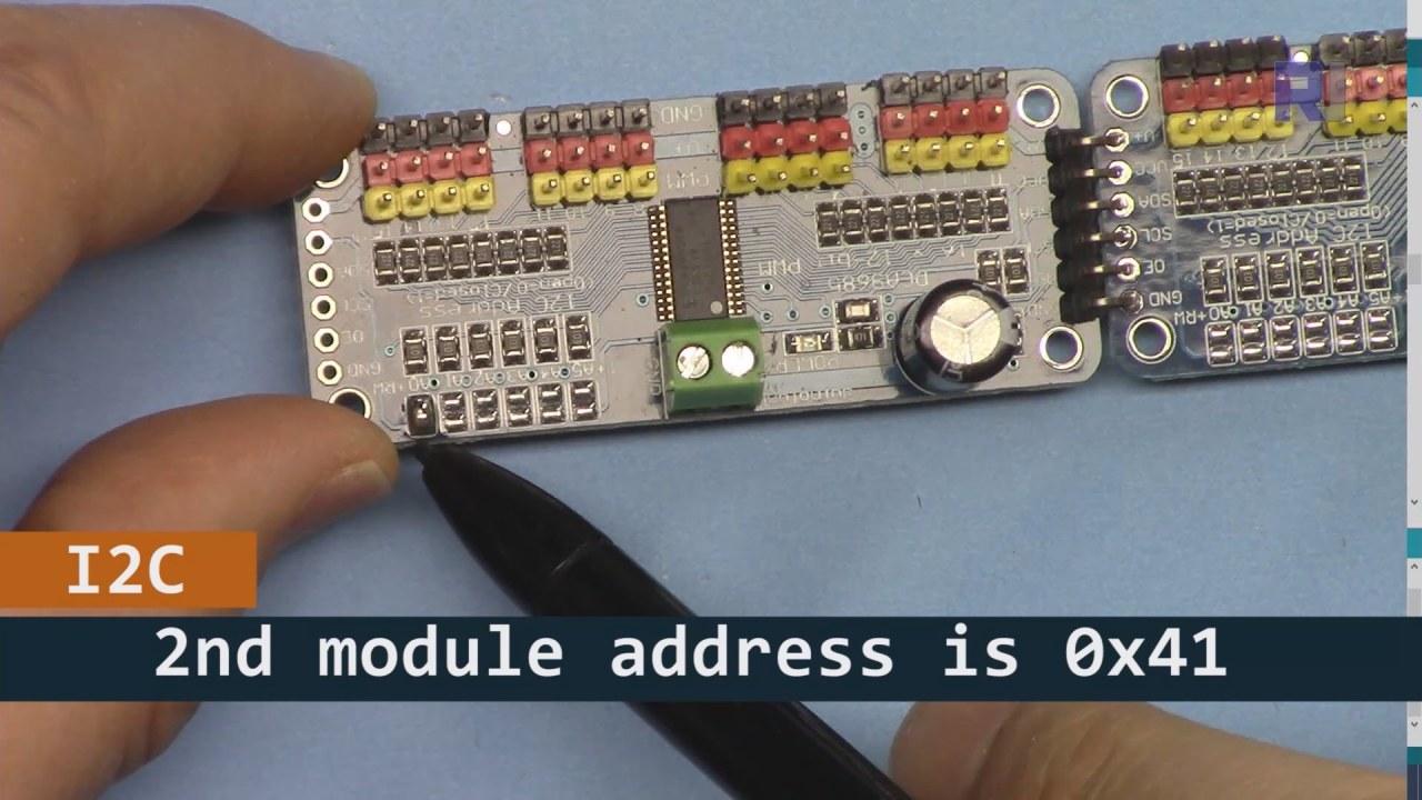
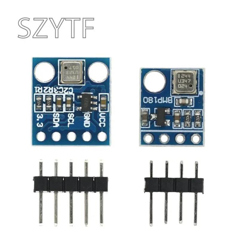
如上图所示,您必须对板子 2 上显示的引脚进行焊接,并且它们必须与板子 1 不同。这样我们将拥有不同的 I2C 地址,您就可以控制该板。
代码示例与教程
让我们来看看初始化PCA9685模块的代码设置部分。在这里,我们为每个板定义地址:
Adafruit_PWMServoDriver board1 = Adafruit_PWMServoDriver(0x40);
Adafruit_PWMServoDriver board2 = Adafruit_PWMServoDriver(0x41);
在这一段中,我们为两个板子创建 PCA9685 驱动程序的实例,指定它们的 I2C 地址。这一设置对于确保我们的 Arduino 能够与两个模块进行通信至关重要。
Thesetup()功能初始化电路板并设置PWM频率:
void setup() {
  Serial.begin(9600);
  board1.begin();
  board2.begin();
  board1.setPWMFreq(60);  // Analog servos run at ~60 Hz updates
  board2.setPWMFreq(60);
}
在这里,我们开始串行通信,并将两个板设置为以60赫兹的频率运行,这对于大多数伺服电机来说是标准的。这确保了在控制伺服电机时操作平稳。
接下来,让我们看一下控制逻辑。loop()功能:
for(int angle = 0; angle < 181; angle += 10) {
  for(int i = 0; i < 16; i++) {
    board1.setPWM(i, 0, angleToPulse(angle));
    board2.setPWM(i, 0, angleToPulse(angle));
  }
}这个循环将角度从0增加到180度,步长为10。对于每个角度,它为两个电路板上的所有伺服器设置PWM信号,使它们能够从0到180度并返回同步移动。angleToPulse()该函数将角度转换为伺服电机的相应脉宽。
演示 / 期待什么
一旦所有线路连接完毕并且代码上传成功,您应该会看到所有32个伺服电机一起运动,平滑地通过角度。如果您按下按钮,它将切换所有伺服电机的状态在开启和关闭之间(在视频中见00:00)。请注意极性反转,并确保您的伺服电机能够承受所提供的电流,以避免过热。
视频时间戳
- 00:00 开始
- 01:18 介绍
- 04:30 准备模块
- 07:56 接线解释
- 10:25 功率要求
- 11:33 代码解释
- 19:54 代码 2 解释(每个板上 8 个伺服器在一起)
- 20:40 演示8个伺服控制一起
- 21:55 演示 所有32个伺服一起移动
- 22:28 按钮的代码解释
- 24:43 按钮接线说明
- 25:12 按钮开关使用演示
图像


本教程是……的一部分: 使用 PCA9685 控制 16 或 32 伺服电机
/*
 * Original source: https://github.com/adafruit/Adafruit-PWM-Servo-Driver-Library
 *
 * This is the Arduino code to use two PCA6985 boards and control 32 servo motor
 *
 * This is V3 Video on PCA9685: https://youtu.be/6P21wG7N6t4
 *  get this code and wiring from for this video:  http://robojax.com/RJT249
to learn better: watch the video for details (V1) and demo http://youtu.be/y8X9X10Tn1k


 * Written/updated by Ahmad Shamshiri for Robojax Video channel www.Robojax.com
 * Date: Dec 15, 2019, in Ajax, Ontario, Canada

 * Watch video for this code:
 *
 * Related Videos
V5 video of PCA9685 32 Servo with ESP32 with WiFi https://youtu.be/bvqfv-FrrLM
V4 video of PCA9685 32 Servo with ESP32 (no WiFi): https://youtu.be/JFdXB8Za5Os
V3 video of PCA9685 how to control 32 Servo motors https://youtu.be/6P21wG7N6t4
V2 Video of PCA9685 3 different ways to control Servo motors: https://youtu.be/bal2STaoQ1M
V1 Video introduction to PCA9685 to control 16 Servo  https://youtu.be/y8X9X10Tn1k
 * Disclaimer: this code is "AS IS" and for educational purpose only.


or make donation using PayPal http://robojax.com/L/?id=64

 *  * This code is "AS IS" without warranty or liability. Free to be used as long as you keep this note intact.*
 * This code has been download from Robojax.com
    This program is free software: you can redistribute it and/or modify
    it under the terms of the GNU General Public License as published by
    the Free Software Foundation, either version 3 of the License, or
    (at your option) any later version.

    This program is distributed in the hope that it will be useful,
    but WITHOUT ANY WARRANTY; without even the implied warranty of
    MERCHANTABILITY or FITNESS FOR A PARTICULAR PURPOSE.  See the
    GNU General Public License for more details.

    You should have received a copy of the GNU General Public License
    along with this program.  If not, see <https://www.gnu.org/licenses/>.
 */
#include <Wire.h>
#include <Adafruit_PWMServoDriver.h>

// called this way, it uses the default address 0x40
Adafruit_PWMServoDriver board1 = Adafruit_PWMServoDriver(0x40);
Adafruit_PWMServoDriver board2 = Adafruit_PWMServoDriver(0x41);

// Depending on your servo make, the pulse width min and max may vary, you
// want these to be as small/large as possible without hitting the hard stop
// for max range. You'll have to tweak them as necessary to match the servos you
// have!
// Watch video V1 to understand the two lines below: http://youtu.be/y8X9X10Tn1k
#define SERVOMIN  125 // this is the 'minimum' pulse length count (out of 4096)
#define SERVOMAX  575 // this is the 'maximum' pulse length count (out of 4096)


int servoNumber = 0;

void setup() {
  Serial.begin(9600);
  Serial.println("16 channel Servo test!");

  board1.begin();
  board2.begin();
  board1.setPWMFreq(60);  // Analog servos run at ~60 Hz updates
  board2.setPWMFreq(60);
  //yield();
}

// the code inside loop() has been updated by Robojax
void loop() {


    for( int angle =0; angle<181; angle +=10){
      for(int i=0; i<16; i++)
        {
            board2.setPWM(i, 0, angleToPulse(angle) );
            board1.setPWM(i, 0, angleToPulse(angle) );
        }
    }

// robojax PCA9865 16 channel Servo control
  delay(100);

}

/*
 * angleToPulse(int ang)
 * gets angle in degree and returns the pulse width
 * also prints the value on seial monitor
 * written by Ahmad Nejrabi for Robojax, Robojax.com
 */
int angleToPulse(int ang){
   int pulse = map(ang,0, 180, SERVOMIN,SERVOMAX);// map angle of 0 to 180 to Servo min and Servo max
   Serial.print("Angle: ");Serial.print(ang);
   Serial.print(" pulse: ");Serial.println(pulse);
   return pulse;
}/*
* Original source: https://github.com/adafruit/Adafruit-PWM-Servo-Driver-Library
*
* This is the Arduino code for two PAC6985 board to control 16 servo on each board
* total 32 servos using I2C communication
* get this code and wiring from for this video (V3): http://robojax.com/RJT249
watch the video for details (V2) and demo https://youtu.be/6P21wG7N6t4
* watch the video for details (V1) and demo http://youtu.be/y8X9X10Tn1k
* This code is #3 for V2 Video Watch the video :
* I have got 3 codes as follow:https://youtu.be/bal2STaoQ1M
*
#1-Arduino Code to run one by one all servos from 0 to 180°
#2-Arduino Code to control specific servos with specific angle
#3-Arduino Code to run 2 or all servos at together
* Written/updated by Ahmad Shamshiri for Robojax Video channel www.Robojax.com
* Date: Dec 16, 2017, in Ajax, Ontario, Canada
* Permission granted to share this code given that this
* note is kept with the code.
* Disclaimer: this code is "AS IS" and for educational purpose only.
* this code has been downloaded from http://robojax.com/
or make donation using PayPal http://robojax.com/L/?id=64
* * This code is "AS IS" without warranty or liability. Free to be used as long as you keep this note intact.*
* This code has been download from Robojax.com
This program is free software: you can redistribute it and/or modify
it under the terms of the GNU General Public License as published by
the Free Software Foundation, either version 3 of the License, or
(at your option) any later version.
This program is distributed in the hope that it will be useful,
but WITHOUT ANY WARRANTY; without even the implied warranty of
MERCHANTABILITY or FITNESS FOR A PARTICULAR PURPOSE. See the
GNU General Public License for more details.
You should have received a copy of the GNU General Public License
along with this program. If not, see <https://www.gnu.org/licenses/>.
*/
#include <Wire.h>
#include <Adafruit_PWMServoDriver.h>
// called this way, it uses the default address 0x40
Adafruit_PWMServoDriver board1 = Adafruit_PWMServoDriver(0x40);
Adafruit_PWMServoDriver board2 = Adafruit_PWMServoDriver(0x41);
// Depending on your servo make, the pulse width min and max may vary, you
// want these to be as small/large as possible without hitting the hard stop
// for max range. You'll have to tweak them as necessary to match the servos you
// have!
// Watch video V1 to understand the two lines below: http://youtu.be/y8X9X10Tn1k
#define SERVOMIN 125 // this is the 'minimum' pulse length count (out of 4096)
#define SERVOMAX 575 // this is the 'maximum' pulse length count (out of 4096)
int servoNumber = 0;
void setup() {
Serial.begin(9600);
Serial.println("16 channel Servo test!");
board1.begin();
board2.begin();
board1.setPWMFreq(60); // Analog servos run at ~60 Hz updates
board2.setPWMFreq(60);
//yield();
}
// the code inside loop() has been updated by Robojax
void loop() {
for( int angle =0; angle<181; angle +=10){
for(int i=0; i<8; i++)
{
board2.setPWM(i, 0, angleToPulse(angle) );
board1.setPWM(i, 0, angleToPulse(angle) );
}
}
for( int angle =0; angle<181; angle +=30){
for(int i=8; i<16; i++)
{
board2.setPWM(i, 0, angleToPulse(angle) );
board1.setPWM(i, 0, angleToPulse(angle) );
}
}
// robojax PCA9865 16 channel Servo control
delay(100);
}
/*
* angleToPulse(int ang)
* gets angle in degree and returns the pulse width
* also prints the value on serial monitor
* written by Ahmad Shamshiri for Robojax, Robojax.com
*/
int angleToPulse(int ang){
int pulse = map(ang,0, 180, SERVOMIN,SERVOMAX);// map angle of 0 to 180 to Servo min and Servo max
Serial.print("Angle: ");Serial.print(ang);
Serial.print(" pulse: ");Serial.println(pulse);
return pulse;
}
 /* Original source: https://github.com/adafruit/Adafruit-PWM-Servo-Driver-Library
 *
 * This is the Arduino code for two PAC6985 board  and push button

 * total 32 servos using I2C communication
 * get this code and wiring from for this video (V3):  http://robojax.com/RJT249


 * watch the video for details (V1) and demo http://youtu.be/y8X9X10Tn1k
 *  This code is #3 for V2 Video Watch the video :
 *  I have got 3 codes as follow:https://youtu.be/bal2STaoQ1M
 *
   #1-Arduino Code to run one by one all servos from 0 to 180°
   #2-Arduino Code to control specific servos with specific angle
   #3-Arduino Code to run 2 or all servos at together

 * Written/updated by Ahmad Shamshiri for Robojax Video channel www.Robojax.com
 * Date: Dec 16, 2017, in Ajax, Ontario, Canada
 * Permission granted to share this code given that this
 * note is kept with the code.
 * Disclaimer: this code is "AS IS" and for educational purpose only.


 *  * This code is "AS IS" without warranty or liability. Free to be used as long as you keep this note intact.*
 * This code has been download from Robojax.com
    This program is free software: you can redistribute it and/or modify
    it under the terms of the GNU General Public License as published by
    the Free Software Foundation, either version 3 of the License, or
    (at your option) any later version.

    This program is distributed in the hope that it will be useful,
    but WITHOUT ANY WARRANTY; without even the implied warranty of
    MERCHANTABILITY or FITNESS FOR A PARTICULAR PURPOSE.  See the
    GNU General Public License for more details.

    You should have received a copy of the GNU General Public License
    along with this program.  If not, see <https://www.gnu.org/licenses/>.
 */
#include <Wire.h>
#include <Adafruit_PWMServoDriver.h>

// called this way, it uses the default address 0x40
Adafruit_PWMServoDriver board1 = Adafruit_PWMServoDriver(0x40);
Adafruit_PWMServoDriver board2 = Adafruit_PWMServoDriver(0x41);

// Depending on your servo make, the pulse width min and max may vary, you
// want these to be as small/large as possible without hitting the hard stop
// for max range. You'll have to tweak them as necessary to match the servos you
// have!
// Watch video V1 to understand the two lines below: http://youtu.be/y8X9X10Tn1k
#define SERVOMIN  125 // this is the 'minimum' pulse length count (out of 4096)
#define SERVOMAX  575 // this is the 'maximum' pulse length count (out of 4096)

#define PUSH_BUTTON_PIN 2
#define OE_PIN 8

int boardState= LOW;
int showDebug=0;
int angle = 0;
int angleStep =10;

void setup() {
  Serial.begin(9600);
  Serial.println("16 channel Servo test!");

  board1.begin();
  board2.begin();
  board1.setPWMFreq(60);  // Analog servos run at ~60 Hz updates
  board2.setPWMFreq(60);

  pinMode(PUSH_BUTTON_PIN,INPUT_PULLUP);
  pinMode(OE_PIN, OUTPUT);
  digitalWrite(OE_PIN,LOW);//turn module ON

}

// the code inside loop() has been updated by Robojax
void loop() {
   if(digitalRead(PUSH_BUTTON_PIN) == LOW)
   {
    boardState = 1-boardState;
    Serial.println("push button pressed");
    delay(200); // give the finger time
   }
 digitalWrite(OE_PIN, boardState);
    for( int angle =0; angle<181; angle +=angleStep){
      delay(50);
      for(int i=0; i<16; i++)
        {
          board1.setPWM(i, 0, angleToPulse(angle) );
          board2.setPWM(i, 0, angleToPulse(angle) );
        }
    }

// robojax PCA9865 16 channel Servo control
  delay(100);

}

/*
 * angleToPulse(int ang)
 * gets angle in degree and returns the pulse width
 * also prints the value on serial monitor
 * written by Ahmad Shamshiri for Robojax, Robojax.com
 */
int angleToPulse(int ang){
   int pulse = map(ang,0, 180, SERVOMIN,SERVOMAX);// map angle of 0 to 180 to Servo min and Servo max
  if(showDebug)
  {
   Serial.print("Angle: ");Serial.print(ang);
   Serial.print(" pulse: ");Serial.println(pulse);
  }
   return pulse;
}

/*
 * updateState()
 * @brief reads push buttons and updates values
 * @param none
 * @return no return
 * Written by Ahmad Shamshiri for robojax.com
 * on Nov 01, 2019 at 18:10 in Ajax, Ontario, Canada
 */
void updateState()
{
   if(digitalRead(PUSH_BUTTON_PIN) == LOW)
   {
    boardState = 1-boardState;
    Serial.println("push button pressed");
    delay(200); // give the finger time
   }
   digitalWrite(OE_PIN, boardState);
}//updateState end
|||您可能需要的东西
-
亚马逊从亚马逊购买PCA9685amzn.to
-
易趣在eBay上购买PCA9685ebay.us
-
全球速卖通从AliExpress购买PCA9685s.click.aliexpress.com
-
Banggood从Bangood购买PCA9685banggood.com
资源与参考
尚无可用资源。
文件📁
Arduino 库(zip 格式)
-
Adafruit-PWM-舵机驱动库-主文件
Adafruit-PWM-Servo-Driver-Library-master.zip0.02 MB