Этот учебник является частью: Управление 16 или 32 сервомоторами с помощью PCA9685
Эта подборка обучающих видеороликов поможет вам управлять 32 и более сервомоторами с помощью Arduino UNO, Nano, Mini или ESP32. Все коды прилагаются.

Управление 32 сервомотором с использованием модуля PCA9685 и скетча Arduino V3 #1: Все сервы вместе
В этом учебном пособии мы научимся управлять 32 сервомоторами, используя два модуля управления ШИМ PCA9685, подключенных к Arduino. PCA9685 — это универсальный модуль, который позволяет легко управлять несколькими сервоприводами через I2C-связь. К концу этого проекта вы сможете перемещать все 32 сервомотора синхронно с помощью простого настроя.

Мы также реализуем кнопку, которая может одновременно включать или выключать все сервоприводы. Эта функция добавляет дополнительный уровень контроля и делает проект более интерактивным. Для визуального понимания настройки и кода обязательно посмотрите сопроводительное видео (в видео на 00:00).
Аппаратура объяснена
Ключевым компонентом этого проекта является модуль PCA9685, который обеспечивает 16 каналов для PWM сигналов. Этот модуль использует I2C-данные, с выводами SDA и SCL для передачи данных. Каждый PCA9685 может управлять до 16 сервоприводами, но, каскадируя два модуля, мы можем одновременно управлять 32 сервоприводами.
Arduino служит в качестве контроллера, отправляя команды модулям PCA9685. Каждый сервопривод будет подключен к одному из выходных контактов на PCA9685, что позволит точно контролировать их позиции. Правильное внешнее питание имеет решающее значение, поскольку сервоприводы могут потреблять значительный ток.
Технические характеристики
| Производитель | Адафрут |
|---|---|
| Номер детали | PCA9685 |
| Логическое/входное напряжение | 3.3 В до 5.5 В |
| Сетевое напряжение | 5 В (внешнее для сервоприводов) |
| Выходной ток (на канал) | ~20 мА |
| Пиковый ток (на канал) | ~25 мА |
| Руководство по частоте ШИМ | 40 Гц до 1000 Гц |
| Входные логические пороги | 0.3 В (низкий), 0.7 В (высокий) |
| Падение напряжения / RDS(включено)/ насыщение | ~0,5 В |
| Тепловые пределы | Рабочая температура: от -40°C до +85°C |
| Упаковка | 16-контактный TSSOP |
| Заметки / варианты | Можно соединять несколько плат для расширенного управления |
- Обеспечьте соответствующее питание, чтобы избежать зависания сервопривода.
- Используйте внешнее питание для сервоприводов; Arduino не может обеспечить достаточный ток.
- Подключите землю PCA9685 к земле Arduino.
- Держите контакт OE заземленным, чтобы включить модуль.
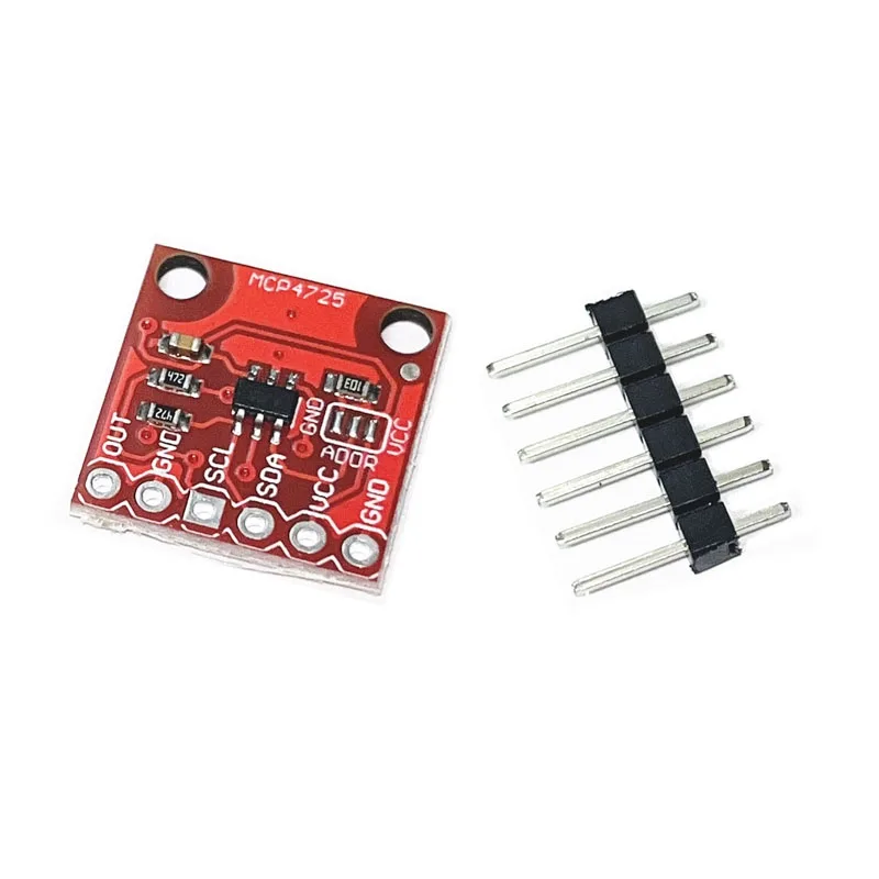
- Обратите внимание на адрес I2C для каждого модуля; по умолчанию 0x40 для первого и 0x41 для второго.
Инструкции по подключению

Чтобы подключить модули PCA9685 и сервоприводы, начните с подключения питания и земли. Подключите вывод VCC на PCA9685 к выводу 5V на Arduino, а вывод земли к GND на Arduino. Для питания сервоприводов используйте внешний источник питания, подключенный к выводу V+ на PCA9685.
Далее подключите выводы SDA и SCL модулей PCA9685 к выводам A4 и A5 Arduino, соответственно. Если вы используете несколько модулей PCA9685, соедините их в цепочку. Убедитесь, что вывод OE подключен к земле для активации выходов. Наконец, подключите сигнал каждого сервопривода к соответствующим выходным выводам PWM на PCA9685 (0-15 для первого модуля и 16-31 для второго модуля).
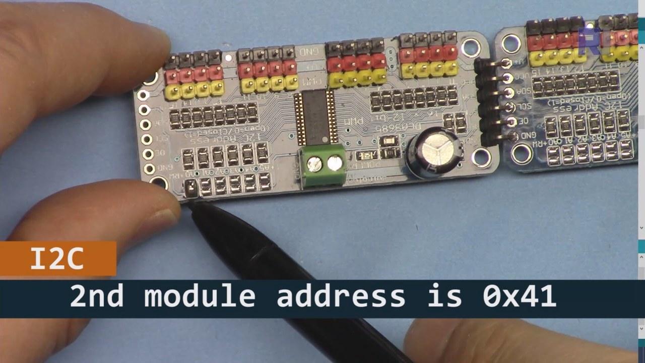
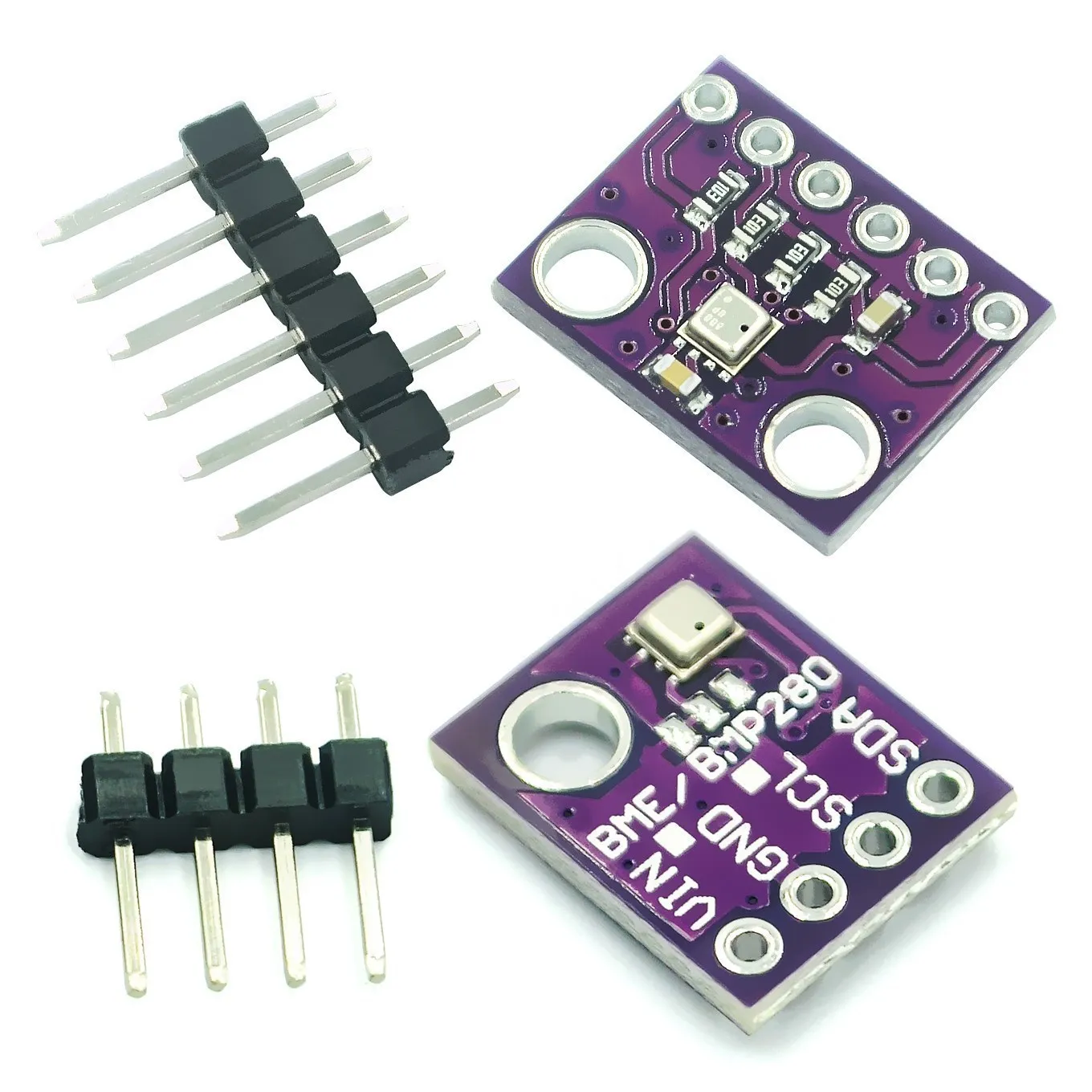
Как показано на изображении выше, вы должны припаять контакты, показанные на плате 2, которые должны отличаться от платы 1. Таким образом, у нас будет разный адрес i2C, и вы сможете управлять платой.
Примеры кода и пошаговое руководство
Давайте рассмотрим часть кода, которая инициализирует модули PCA9685. Здесь мы определяем адреса для каждой платы:
Adafruit_PWMServoDriver board1 = Adafruit_PWMServoDriver(0x40);
Adafruit_PWMServoDriver board2 = Adafruit_PWMServoDriver(0x41);
В этом фрагменте мы создаем экземпляры драйвера PCA9685 для обеих плат, указывая их адреса I2C. Эта настройка имеет решающее значение для обеспечения связи нашего Arduino с обеими модулями.
Thesetup()функция инициализирует платы и устанавливает частоту ШИМ:
void setup() {
  Serial.begin(9600);
  board1.begin();
  board2.begin();
  board1.setPWMFreq(60);  // Analog servos run at ~60 Hz updates
  board2.setPWMFreq(60);
}
Здесь мы начинаем последовательную связь и устанавливаем обе платы на работу с частотой 60 Гц, что является стандартом для большинства сервоприводов. Это обеспечивает плавную работу во время управления сервоприводами.
Далее давайте рассмотрим управляющую логику вloop() функция:
for(int angle = 0; angle < 181; angle += 10) {
  for(int i = 0; i < 16; i++) {
    board1.setPWM(i, 0, angleToPulse(angle));
    board2.setPWM(i, 0, angleToPulse(angle));
  }
}
Этот цикл увеличивает угол от 0 до 180 градусов с шагом 10. Для каждого угла он устанавливает сигнал ШИМ для всех сервоприводов на обеих платах, позволяя им двигаться синхронно от 0 до 180 градусов и обратно.angleToPulse()функция преобразует угол в соответствующую ширину импульса для сервоприводов.
Демонстрация / Что ожидать
Как только всё будет подключено и код загружен, вы должны увидеть, как все 32 сервопривода движутся вместе, плавно проходя углы. Если вы нажмете кнопку, она переключит состояние всех сервоприводов между включенным и выключенным (в видео на 00:00). Будьте осторожны с обратной полярностью и убедитесь, что ваши сервоприводы рассчитаны на подаваемый ток, чтобы избежать перегрева.
Временные метки видео
- 00:00 Начало
- 01:18 Введение
- 04:30 Подготовка к модулям
- 07:56 объяснение проводки
- 10:25 Требование к питанию
- 11:33 Объяснение кода
- 19:54 Объяснение кода 2 (8 сервоприводов вместе на каждой плате)
- 20:40 Демонстрация 8 сервоуправления вместе
- 21:55 Демонстрация Все 32 сервопривода движутся вместе
- 22:28 Объяснение кода для кнопки-перехода
- 24:43 Объяснение проводки для кнопки нажимания
- 25:12 Демонстрация использования кнопочного переключателя
Изображения


Этот учебник является частью: Управление 16 или 32 сервомоторами с помощью PCA9685
- Код Arduino и видео для сервоконтроллера PCA9685 на 16 каналов с разрешением 12 бит V1
- Управление 16 сервомоторами с помощью модуля PCA9685 и скетча Arduino V2 #1: По одному
- Управление 16 серводвигателями с помощью модуля PCA9685 и скетча Arduino V2: Управление отдельным сервоприводом
- Controlling 16 Servo Motors Using a PCA9685 Module and Arduino V2 Sketch #3: All Servos Together
- Управление 32 сервомоторами с помощью модуля PCA9685 и ESP32 V4
- Управление 32 сервомоторами по Wi-Fi с использованием ESP32 и PCA9685 через настольный или мобильный телефон V5
/*
 * Original source: https://github.com/adafruit/Adafruit-PWM-Servo-Driver-Library
 *
 * This is the Arduino code to use two PCA6985 boards and control 32 servo motor
 *
 * This is V3 Video on PCA9685: https://youtu.be/6P21wG7N6t4
 *  get this code and wiring from for this video:  http://robojax.com/RJT249
to learn better: watch the video for details (V1) and demo http://youtu.be/y8X9X10Tn1k


 * Written/updated by Ahmad Shamshiri for Robojax Video channel www.Robojax.com
 * Date: Dec 15, 2019, in Ajax, Ontario, Canada

 * Watch video for this code:
 *
 * Related Videos
V5 video of PCA9685 32 Servo with ESP32 with WiFi https://youtu.be/bvqfv-FrrLM
V4 video of PCA9685 32 Servo with ESP32 (no WiFi): https://youtu.be/JFdXB8Za5Os
V3 video of PCA9685 how to control 32 Servo motors https://youtu.be/6P21wG7N6t4
V2 Video of PCA9685 3 different ways to control Servo motors: https://youtu.be/bal2STaoQ1M
V1 Video introduction to PCA9685 to control 16 Servo  https://youtu.be/y8X9X10Tn1k
 * Disclaimer: this code is "AS IS" and for educational purpose only.


or make donation using PayPal http://robojax.com/L/?id=64

 *  * This code is "AS IS" without warranty or liability. Free to be used as long as you keep this note intact.*
 * This code has been download from Robojax.com
    This program is free software: you can redistribute it and/or modify
    it under the terms of the GNU General Public License as published by
    the Free Software Foundation, either version 3 of the License, or
    (at your option) any later version.

    This program is distributed in the hope that it will be useful,
    but WITHOUT ANY WARRANTY; without even the implied warranty of
    MERCHANTABILITY or FITNESS FOR A PARTICULAR PURPOSE.  See the
    GNU General Public License for more details.

    You should have received a copy of the GNU General Public License
    along with this program.  If not, see <https://www.gnu.org/licenses/>.
 */
#include <Wire.h>
#include <Adafruit_PWMServoDriver.h>

// called this way, it uses the default address 0x40
Adafruit_PWMServoDriver board1 = Adafruit_PWMServoDriver(0x40);
Adafruit_PWMServoDriver board2 = Adafruit_PWMServoDriver(0x41);

// Depending on your servo make, the pulse width min and max may vary, you
// want these to be as small/large as possible without hitting the hard stop
// for max range. You'll have to tweak them as necessary to match the servos you
// have!
// Watch video V1 to understand the two lines below: http://youtu.be/y8X9X10Tn1k
#define SERVOMIN  125 // this is the 'minimum' pulse length count (out of 4096)
#define SERVOMAX  575 // this is the 'maximum' pulse length count (out of 4096)


int servoNumber = 0;

void setup() {
  Serial.begin(9600);
  Serial.println("16 channel Servo test!");

  board1.begin();
  board2.begin();
  board1.setPWMFreq(60);  // Analog servos run at ~60 Hz updates
  board2.setPWMFreq(60);
  //yield();
}

// the code inside loop() has been updated by Robojax
void loop() {


    for( int angle =0; angle<181; angle +=10){
      for(int i=0; i<16; i++)
        {
            board2.setPWM(i, 0, angleToPulse(angle) );
            board1.setPWM(i, 0, angleToPulse(angle) );
        }
    }

// robojax PCA9865 16 channel Servo control
  delay(100);

}

/*
 * angleToPulse(int ang)
 * gets angle in degree and returns the pulse width
 * also prints the value on seial monitor
 * written by Ahmad Nejrabi for Robojax, Robojax.com
 */
int angleToPulse(int ang){
   int pulse = map(ang,0, 180, SERVOMIN,SERVOMAX);// map angle of 0 to 180 to Servo min and Servo max
   Serial.print("Angle: ");Serial.print(ang);
   Serial.print(" pulse: ");Serial.println(pulse);
   return pulse;
}/*
* Original source: https://github.com/adafruit/Adafruit-PWM-Servo-Driver-Library
*
* This is the Arduino code for two PAC6985 board to control 16 servo on each board
* total 32 servos using I2C communication
* get this code and wiring from for this video (V3): http://robojax.com/RJT249
watch the video for details (V2) and demo https://youtu.be/6P21wG7N6t4
* watch the video for details (V1) and demo http://youtu.be/y8X9X10Tn1k
* This code is #3 for V2 Video Watch the video :
* I have got 3 codes as follow:https://youtu.be/bal2STaoQ1M
*
#1-Arduino Code to run one by one all servos from 0 to 180°
#2-Arduino Code to control specific servos with specific angle
#3-Arduino Code to run 2 or all servos at together
* Written/updated by Ahmad Shamshiri for Robojax Video channel www.Robojax.com
* Date: Dec 16, 2017, in Ajax, Ontario, Canada
* Permission granted to share this code given that this
* note is kept with the code.
* Disclaimer: this code is "AS IS" and for educational purpose only.
* this code has been downloaded from http://robojax.com/
or make donation using PayPal http://robojax.com/L/?id=64
* * This code is "AS IS" without warranty or liability. Free to be used as long as you keep this note intact.*
* This code has been download from Robojax.com
This program is free software: you can redistribute it and/or modify
it under the terms of the GNU General Public License as published by
the Free Software Foundation, either version 3 of the License, or
(at your option) any later version.
This program is distributed in the hope that it will be useful,
but WITHOUT ANY WARRANTY; without even the implied warranty of
MERCHANTABILITY or FITNESS FOR A PARTICULAR PURPOSE. See the
GNU General Public License for more details.
You should have received a copy of the GNU General Public License
along with this program. If not, see <https://www.gnu.org/licenses/>.
*/
#include <Wire.h>
#include <Adafruit_PWMServoDriver.h>
// called this way, it uses the default address 0x40
Adafruit_PWMServoDriver board1 = Adafruit_PWMServoDriver(0x40);
Adafruit_PWMServoDriver board2 = Adafruit_PWMServoDriver(0x41);
// Depending on your servo make, the pulse width min and max may vary, you
// want these to be as small/large as possible without hitting the hard stop
// for max range. You'll have to tweak them as necessary to match the servos you
// have!
// Watch video V1 to understand the two lines below: http://youtu.be/y8X9X10Tn1k
#define SERVOMIN 125 // this is the 'minimum' pulse length count (out of 4096)
#define SERVOMAX 575 // this is the 'maximum' pulse length count (out of 4096)
int servoNumber = 0;
void setup() {
Serial.begin(9600);
Serial.println("16 channel Servo test!");
board1.begin();
board2.begin();
board1.setPWMFreq(60); // Analog servos run at ~60 Hz updates
board2.setPWMFreq(60);
//yield();
}
// the code inside loop() has been updated by Robojax
void loop() {
for( int angle =0; angle<181; angle +=10){
for(int i=0; i<8; i++)
{
board2.setPWM(i, 0, angleToPulse(angle) );
board1.setPWM(i, 0, angleToPulse(angle) );
}
}
for( int angle =0; angle<181; angle +=30){
for(int i=8; i<16; i++)
{
board2.setPWM(i, 0, angleToPulse(angle) );
board1.setPWM(i, 0, angleToPulse(angle) );
}
}
// robojax PCA9865 16 channel Servo control
delay(100);
}
/*
* angleToPulse(int ang)
* gets angle in degree and returns the pulse width
* also prints the value on serial monitor
* written by Ahmad Shamshiri for Robojax, Robojax.com
*/
int angleToPulse(int ang){
int pulse = map(ang,0, 180, SERVOMIN,SERVOMAX);// map angle of 0 to 180 to Servo min and Servo max
Serial.print("Angle: ");Serial.print(ang);
Serial.print(" pulse: ");Serial.println(pulse);
return pulse;
}
 /* Original source: https://github.com/adafruit/Adafruit-PWM-Servo-Driver-Library
 *
 * This is the Arduino code for two PAC6985 board  and push button

 * total 32 servos using I2C communication
 * get this code and wiring from for this video (V3):  http://robojax.com/RJT249


 * watch the video for details (V1) and demo http://youtu.be/y8X9X10Tn1k
 *  This code is #3 for V2 Video Watch the video :
 *  I have got 3 codes as follow:https://youtu.be/bal2STaoQ1M
 *
   #1-Arduino Code to run one by one all servos from 0 to 180°
   #2-Arduino Code to control specific servos with specific angle
   #3-Arduino Code to run 2 or all servos at together

 * Written/updated by Ahmad Shamshiri for Robojax Video channel www.Robojax.com
 * Date: Dec 16, 2017, in Ajax, Ontario, Canada
 * Permission granted to share this code given that this
 * note is kept with the code.
 * Disclaimer: this code is "AS IS" and for educational purpose only.


 *  * This code is "AS IS" without warranty or liability. Free to be used as long as you keep this note intact.*
 * This code has been download from Robojax.com
    This program is free software: you can redistribute it and/or modify
    it under the terms of the GNU General Public License as published by
    the Free Software Foundation, either version 3 of the License, or
    (at your option) any later version.

    This program is distributed in the hope that it will be useful,
    but WITHOUT ANY WARRANTY; without even the implied warranty of
    MERCHANTABILITY or FITNESS FOR A PARTICULAR PURPOSE.  See the
    GNU General Public License for more details.

    You should have received a copy of the GNU General Public License
    along with this program.  If not, see <https://www.gnu.org/licenses/>.
 */
#include <Wire.h>
#include <Adafruit_PWMServoDriver.h>

// called this way, it uses the default address 0x40
Adafruit_PWMServoDriver board1 = Adafruit_PWMServoDriver(0x40);
Adafruit_PWMServoDriver board2 = Adafruit_PWMServoDriver(0x41);

// Depending on your servo make, the pulse width min and max may vary, you
// want these to be as small/large as possible without hitting the hard stop
// for max range. You'll have to tweak them as necessary to match the servos you
// have!
// Watch video V1 to understand the two lines below: http://youtu.be/y8X9X10Tn1k
#define SERVOMIN  125 // this is the 'minimum' pulse length count (out of 4096)
#define SERVOMAX  575 // this is the 'maximum' pulse length count (out of 4096)

#define PUSH_BUTTON_PIN 2
#define OE_PIN 8

int boardState= LOW;
int showDebug=0;
int angle = 0;
int angleStep =10;

void setup() {
  Serial.begin(9600);
  Serial.println("16 channel Servo test!");

  board1.begin();
  board2.begin();
  board1.setPWMFreq(60);  // Analog servos run at ~60 Hz updates
  board2.setPWMFreq(60);

  pinMode(PUSH_BUTTON_PIN,INPUT_PULLUP);
  pinMode(OE_PIN, OUTPUT);
  digitalWrite(OE_PIN,LOW);//turn module ON

}

// the code inside loop() has been updated by Robojax
void loop() {
   if(digitalRead(PUSH_BUTTON_PIN) == LOW)
   {
    boardState = 1-boardState;
    Serial.println("push button pressed");
    delay(200); // give the finger time
   }
 digitalWrite(OE_PIN, boardState);
    for( int angle =0; angle<181; angle +=angleStep){
      delay(50);
      for(int i=0; i<16; i++)
        {
          board1.setPWM(i, 0, angleToPulse(angle) );
          board2.setPWM(i, 0, angleToPulse(angle) );
        }
    }

// robojax PCA9865 16 channel Servo control
  delay(100);

}

/*
 * angleToPulse(int ang)
 * gets angle in degree and returns the pulse width
 * also prints the value on serial monitor
 * written by Ahmad Shamshiri for Robojax, Robojax.com
 */
int angleToPulse(int ang){
   int pulse = map(ang,0, 180, SERVOMIN,SERVOMAX);// map angle of 0 to 180 to Servo min and Servo max
  if(showDebug)
  {
   Serial.print("Angle: ");Serial.print(ang);
   Serial.print(" pulse: ");Serial.println(pulse);
  }
   return pulse;
}

/*
 * updateState()
 * @brief reads push buttons and updates values
 * @param none
 * @return no return
 * Written by Ahmad Shamshiri for robojax.com
 * on Nov 01, 2019 at 18:10 in Ajax, Ontario, Canada
 */
void updateState()
{
   if(digitalRead(PUSH_BUTTON_PIN) == LOW)
   {
    boardState = 1-boardState;
    Serial.println("push button pressed");
    delay(200); // give the finger time
   }
   digitalWrite(OE_PIN, boardState);
}//updateState end
Вещи, которые могут вам понадобиться
-
АмазонкаКупите PCA9685 на Amazonamzn.to
-
eBayКупите PCA9685 на eBayebay.us
-
АлиЭкспрессКупите PCA9685 на AliExpresss.click.aliexpress.com
-
БанггудПриобретите PCA9685 на Bangoodbanggood.com
Ресурсы и ссылки
Ресурсов пока нет.
Файлы📁
Библиотеки Arduino (zip)
-
Adafruit-PWM-Сервопривод-Менеджер-Библиотека-мастер
Adafruit-PWM-Servo-Driver-Library-master.zip0.02 MB