このチュートリアルはの一部です: PCA9685で16または32個のサーボモーターを制御する
これらのビデオ付きチュートリアル集は、Arduino UNO、Nano、Mini、またはESP32を使用して32個以上のサーボモーターを制御するのに役立ちます。すべてのコードは提供されています。

PCA9685モジュールとArduino V3スケッチを使用して32個のサーボモーターを制御する #1:すべてのサーボを一緒に
このチュートリアルでは、Arduinoに接続された2つのPCA9685 PWMドライバーモジュールを使用して、32台のサーボモーターを制御する方法を学びます。PCA9685は、I2C通信を介して複数のサーボを簡単に制御できる多機能モジュールです。このプロジェクトの終わりまでには、シンプルな設定で32台のサーボを一斉に動かすことができるようになります。

すべてのサーボを同時にオンまたはオフにできるプッシュボタンも実装します。この機能は制御のさらなる層を追加し、プロジェクトをよりインタラクティブにします。セットアップとコードの視覚的理解のために、付随するビデオ(ビデオは00:00にあります)を必ずチェックしてください。
ハードウェアの説明
このプロジェクトの主要なコンポーネントはPCA9685モジュールで、16チャンネルのPWM信号を提供します。このモジュールはI2C通信を使用し、SDAおよびSCLピンがデータ送信を処理します。各PCA9685は最大16個のサーボを制御できますが、2つのモジュールをカスケード接続することで、同時に32個のサーボを制御できます。
Arduinoはコントローラーとして機能し、PCA9685モジュールにコマンドを送ります。各サーボモーターはPCA9685の出力ピンの1つに接続され、位置を正確に制御できるようになります。サーボはかなりの電流を引き込む可能性があるため、適切な外部電源が重要です。
データシートの詳細
| メーカー | アダフルーツ |
|---|---|
| 部品番号 | PCA9685 |
| 論理/入出力電圧 | 3.3 Vから5.5 V |
| 供給電圧 | 5V(サーボ用外部) |
| 出力電流(チャネルごと) | 約20 mA |
| ピーク電流(チャネルごと) | 約25 mA |
| PWM周波数ガイダンス | 40 Hzから1000 Hz |
| 入力論理しきい値 | 0.3 V(低)、0.7 V(高) |
| 電圧降下 / RDS(on)/ 飽和度 | 約0.5 V |
| 熱的限界 | 動作温度:-40°Cから+85°C |
| パッケージ | 16ピン TSSOP |
| ノート / バリアント | 複数のボードを連結して拡張した制御が可能です。 |
- サーボがストールしないように適切な電源を確保してください。
- サーボ用に外部電源を使用してください。Arduinoは十分な電流を供給できません。
- PCA9685のグラウンドをArduinoのグラウンドに接続します。
- OEピンを接地してモジュールを有効にしてください。
- 各モジュールのI2Cアドレスに注意してください。最初のモジュールのデフォルトは0x40、2番目のモジュールのデフォルトは0x41です。
配線指示

PCA9685モジュールとサーボを配線するには、まず電源とグラウンドを接続します。PCA9685のVCCピンをArduinoの5Vピンに接続し、グラウンドピンをArduinoのGNDに接続します。サーボの電源には、PCA9685のV+ピンに接続された外部電源を使用します。
次に、PCA9685モジュールのSDAおよびSCLピンをそれぞれArduinoのA4およびA5ピンに接続します。複数のPCA9685モジュールを使用する場合は、デイジーチェーンで接続します。出力を有効にするために、OEピンをグラウンドに接続していることを確認してください。最後に、それぞれのサーボの信号線をPCA9685のそれぞれのPWM出力ピンに接続します(最初のモジュールは0-15、2番目のモジュールは16-31)。
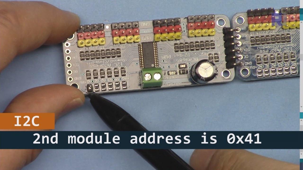
上の画像に示されているように、基板2のピンをはんだ付けする必要があり、基板1とは異なる必要があります。この方法で異なるi2Cアドレスを持つことができ、基板を制御することができます。
コード例とウォークスルー
PCA9685モジュールを初期化するコードのセットアップ部分を見てみましょう。ここでは、各ボードのアドレスを定義します。
Adafruit_PWMServoDriver board1 = Adafruit_PWMServoDriver(0x40);
Adafruit_PWMServoDriver board2 = Adafruit_PWMServoDriver(0x41);
この抜粋では、両方のボード用にPCA9685ドライバーのインスタンスを作成し、それぞれのI2Cアドレスを指定します。この設定は、私たちのArduinoが両方のモジュールと通信できることを保証するために重要です。
ザsetup()関数はボードを初期化し、PWM周波数を設定します。
void setup() {
  Serial.begin(9600);
  board1.begin();
  board2.begin();
  board1.setPWMFreq(60);  // Analog servos run at ~60 Hz updates
  board2.setPWMFreq(60);
}
ここでは、シリアル通信を開始し、両方のボードを60 Hzの周波数で動作するように設定します。これはほとんどのサーボに標準的なものです。これにより、サーボを制御する際にスムーズな動作が保証されます。
次に、制御論理を見てみましょう。loop()関数:
for(int angle = 0; angle < 181; angle += 10) {
  for(int i = 0; i < 16; i++) {
    board1.setPWM(i, 0, angleToPulse(angle));
    board2.setPWM(i, 0, angleToPulse(angle));
  }
}このループは、角度を0度から180度まで10度刻みで増加させます。各角度に対して、両方のボード上のすべてのサーボにPWM信号を設定し、サーボが0度から180度まで一斉に動き、再び戻ることを可能にします。angleToPulse()関数は角度をサーボ用の対応するパルス幅に変換します。
デモンストレーション / 期待できること
すべてが配線され、コードがアップロードされると、32個のサーボが一緒に動き、角度をスムーズに移動するのが見えるはずです。プッシュボタンを押すと、すべてのサーボの状態がオンとオフの間で切り替わります(動画の00:00で)。極性が逆になっていないかに注意し、サーボが供給される電流に対して定格であることを確認して、過熱を避けてください。
ビデオのタイムスタンプ
- 00:00 スタート
- 01:18 イントロダクション
- 04:30 モジュールの準備中
- 07:56 配線の説明
- 10:25 電力要件
- 11:33 コードの説明
- 19:54 コード2の説明(各ボードに8つのサーボが一緒に)
- 20:40 デモンストレーション 8 サーボ制御の連携
- 21:55 デモンストレーション すべての32サーボが一緒に動く
- 22:28 プッシュボタンのコードが説明されています
- 24:43 プッシュボタンの配線の説明
- 25:12 プッシュボタンスイッチの使用デモンストレーション
画像


このチュートリアルはの一部です: PCA9685で16または32個のサーボモーターを制御する
- PCA9685 16チャンネル 12ビット サーボコントローラ V1 用の Arduino コードとビデオ
- PCA9685モジュールとArduino V2スケッチを使用して16個のサーボモーターを制御する #1: 一つずつ
- PCA9685モジュールとArduino V2スケッチを使用した16個のサーボモーターの制御:個別サーボ制御
- Controlling 16 Servo Motors Using a PCA9685 Module and Arduino V2 Sketch #3: All Servos Together
- PCA9685モジュールとESP32 V4を使用して32サーボモーターを制御する
- Wi-Fiを介してESP32とPCA9685を使用し、デスクトップまたはモバイルフォンから32サーボを制御する V5
/*
 * Original source: https://github.com/adafruit/Adafruit-PWM-Servo-Driver-Library
 *
 * This is the Arduino code to use two PCA6985 boards and control 32 servo motor
 *
 * This is V3 Video on PCA9685: https://youtu.be/6P21wG7N6t4
 *  get this code and wiring from for this video:  http://robojax.com/RJT249
to learn better: watch the video for details (V1) and demo http://youtu.be/y8X9X10Tn1k


 * Written/updated by Ahmad Shamshiri for Robojax Video channel www.Robojax.com
 * Date: Dec 15, 2019, in Ajax, Ontario, Canada

 * Watch video for this code:
 *
 * Related Videos
V5 video of PCA9685 32 Servo with ESP32 with WiFi https://youtu.be/bvqfv-FrrLM
V4 video of PCA9685 32 Servo with ESP32 (no WiFi): https://youtu.be/JFdXB8Za5Os
V3 video of PCA9685 how to control 32 Servo motors https://youtu.be/6P21wG7N6t4
V2 Video of PCA9685 3 different ways to control Servo motors: https://youtu.be/bal2STaoQ1M
V1 Video introduction to PCA9685 to control 16 Servo  https://youtu.be/y8X9X10Tn1k
 * Disclaimer: this code is "AS IS" and for educational purpose only.


or make donation using PayPal http://robojax.com/L/?id=64

 *  * This code is "AS IS" without warranty or liability. Free to be used as long as you keep this note intact.*
 * This code has been download from Robojax.com
    This program is free software: you can redistribute it and/or modify
    it under the terms of the GNU General Public License as published by
    the Free Software Foundation, either version 3 of the License, or
    (at your option) any later version.

    This program is distributed in the hope that it will be useful,
    but WITHOUT ANY WARRANTY; without even the implied warranty of
    MERCHANTABILITY or FITNESS FOR A PARTICULAR PURPOSE.  See the
    GNU General Public License for more details.

    You should have received a copy of the GNU General Public License
    along with this program.  If not, see <https://www.gnu.org/licenses/>.
 */
#include <Wire.h>
#include <Adafruit_PWMServoDriver.h>

// called this way, it uses the default address 0x40
Adafruit_PWMServoDriver board1 = Adafruit_PWMServoDriver(0x40);
Adafruit_PWMServoDriver board2 = Adafruit_PWMServoDriver(0x41);

// Depending on your servo make, the pulse width min and max may vary, you
// want these to be as small/large as possible without hitting the hard stop
// for max range. You'll have to tweak them as necessary to match the servos you
// have!
// Watch video V1 to understand the two lines below: http://youtu.be/y8X9X10Tn1k
#define SERVOMIN  125 // this is the 'minimum' pulse length count (out of 4096)
#define SERVOMAX  575 // this is the 'maximum' pulse length count (out of 4096)


int servoNumber = 0;

void setup() {
  Serial.begin(9600);
  Serial.println("16 channel Servo test!");

  board1.begin();
  board2.begin();
  board1.setPWMFreq(60);  // Analog servos run at ~60 Hz updates
  board2.setPWMFreq(60);
  //yield();
}

// the code inside loop() has been updated by Robojax
void loop() {


    for( int angle =0; angle<181; angle +=10){
      for(int i=0; i<16; i++)
        {
            board2.setPWM(i, 0, angleToPulse(angle) );
            board1.setPWM(i, 0, angleToPulse(angle) );
        }
    }

// robojax PCA9865 16 channel Servo control
  delay(100);

}

/*
 * angleToPulse(int ang)
 * gets angle in degree and returns the pulse width
 * also prints the value on seial monitor
 * written by Ahmad Nejrabi for Robojax, Robojax.com
 */
int angleToPulse(int ang){
   int pulse = map(ang,0, 180, SERVOMIN,SERVOMAX);// map angle of 0 to 180 to Servo min and Servo max
   Serial.print("Angle: ");Serial.print(ang);
   Serial.print(" pulse: ");Serial.println(pulse);
   return pulse;
}/*
* Original source: https://github.com/adafruit/Adafruit-PWM-Servo-Driver-Library
*
* This is the Arduino code for two PAC6985 board to control 16 servo on each board
* total 32 servos using I2C communication
* get this code and wiring from for this video (V3): http://robojax.com/RJT249
watch the video for details (V2) and demo https://youtu.be/6P21wG7N6t4
* watch the video for details (V1) and demo http://youtu.be/y8X9X10Tn1k
* This code is #3 for V2 Video Watch the video :
* I have got 3 codes as follow:https://youtu.be/bal2STaoQ1M
*
#1-Arduino Code to run one by one all servos from 0 to 180°
#2-Arduino Code to control specific servos with specific angle
#3-Arduino Code to run 2 or all servos at together
* Written/updated by Ahmad Shamshiri for Robojax Video channel www.Robojax.com
* Date: Dec 16, 2017, in Ajax, Ontario, Canada
* Permission granted to share this code given that this
* note is kept with the code.
* Disclaimer: this code is "AS IS" and for educational purpose only.
* this code has been downloaded from http://robojax.com/
or make donation using PayPal http://robojax.com/L/?id=64
* * This code is "AS IS" without warranty or liability. Free to be used as long as you keep this note intact.*
* This code has been download from Robojax.com
This program is free software: you can redistribute it and/or modify
it under the terms of the GNU General Public License as published by
the Free Software Foundation, either version 3 of the License, or
(at your option) any later version.
This program is distributed in the hope that it will be useful,
but WITHOUT ANY WARRANTY; without even the implied warranty of
MERCHANTABILITY or FITNESS FOR A PARTICULAR PURPOSE. See the
GNU General Public License for more details.
You should have received a copy of the GNU General Public License
along with this program. If not, see <https://www.gnu.org/licenses/>.
*/
#include <Wire.h>
#include <Adafruit_PWMServoDriver.h>
// called this way, it uses the default address 0x40
Adafruit_PWMServoDriver board1 = Adafruit_PWMServoDriver(0x40);
Adafruit_PWMServoDriver board2 = Adafruit_PWMServoDriver(0x41);
// Depending on your servo make, the pulse width min and max may vary, you
// want these to be as small/large as possible without hitting the hard stop
// for max range. You'll have to tweak them as necessary to match the servos you
// have!
// Watch video V1 to understand the two lines below: http://youtu.be/y8X9X10Tn1k
#define SERVOMIN 125 // this is the 'minimum' pulse length count (out of 4096)
#define SERVOMAX 575 // this is the 'maximum' pulse length count (out of 4096)
int servoNumber = 0;
void setup() {
Serial.begin(9600);
Serial.println("16 channel Servo test!");
board1.begin();
board2.begin();
board1.setPWMFreq(60); // Analog servos run at ~60 Hz updates
board2.setPWMFreq(60);
//yield();
}
// the code inside loop() has been updated by Robojax
void loop() {
for( int angle =0; angle<181; angle +=10){
for(int i=0; i<8; i++)
{
board2.setPWM(i, 0, angleToPulse(angle) );
board1.setPWM(i, 0, angleToPulse(angle) );
}
}
for( int angle =0; angle<181; angle +=30){
for(int i=8; i<16; i++)
{
board2.setPWM(i, 0, angleToPulse(angle) );
board1.setPWM(i, 0, angleToPulse(angle) );
}
}
// robojax PCA9865 16 channel Servo control
delay(100);
}
/*
* angleToPulse(int ang)
* gets angle in degree and returns the pulse width
* also prints the value on serial monitor
* written by Ahmad Shamshiri for Robojax, Robojax.com
*/
int angleToPulse(int ang){
int pulse = map(ang,0, 180, SERVOMIN,SERVOMAX);// map angle of 0 to 180 to Servo min and Servo max
Serial.print("Angle: ");Serial.print(ang);
Serial.print(" pulse: ");Serial.println(pulse);
return pulse;
}
 /* Original source: https://github.com/adafruit/Adafruit-PWM-Servo-Driver-Library
 *
 * This is the Arduino code for two PAC6985 board  and push button

 * total 32 servos using I2C communication
 * get this code and wiring from for this video (V3):  http://robojax.com/RJT249


 * watch the video for details (V1) and demo http://youtu.be/y8X9X10Tn1k
 *  This code is #3 for V2 Video Watch the video :
 *  I have got 3 codes as follow:https://youtu.be/bal2STaoQ1M
 *
   #1-Arduino Code to run one by one all servos from 0 to 180°
   #2-Arduino Code to control specific servos with specific angle
   #3-Arduino Code to run 2 or all servos at together

 * Written/updated by Ahmad Shamshiri for Robojax Video channel www.Robojax.com
 * Date: Dec 16, 2017, in Ajax, Ontario, Canada
 * Permission granted to share this code given that this
 * note is kept with the code.
 * Disclaimer: this code is "AS IS" and for educational purpose only.


 *  * This code is "AS IS" without warranty or liability. Free to be used as long as you keep this note intact.*
 * This code has been download from Robojax.com
    This program is free software: you can redistribute it and/or modify
    it under the terms of the GNU General Public License as published by
    the Free Software Foundation, either version 3 of the License, or
    (at your option) any later version.

    This program is distributed in the hope that it will be useful,
    but WITHOUT ANY WARRANTY; without even the implied warranty of
    MERCHANTABILITY or FITNESS FOR A PARTICULAR PURPOSE.  See the
    GNU General Public License for more details.

    You should have received a copy of the GNU General Public License
    along with this program.  If not, see <https://www.gnu.org/licenses/>.
 */
#include <Wire.h>
#include <Adafruit_PWMServoDriver.h>

// called this way, it uses the default address 0x40
Adafruit_PWMServoDriver board1 = Adafruit_PWMServoDriver(0x40);
Adafruit_PWMServoDriver board2 = Adafruit_PWMServoDriver(0x41);

// Depending on your servo make, the pulse width min and max may vary, you
// want these to be as small/large as possible without hitting the hard stop
// for max range. You'll have to tweak them as necessary to match the servos you
// have!
// Watch video V1 to understand the two lines below: http://youtu.be/y8X9X10Tn1k
#define SERVOMIN  125 // this is the 'minimum' pulse length count (out of 4096)
#define SERVOMAX  575 // this is the 'maximum' pulse length count (out of 4096)

#define PUSH_BUTTON_PIN 2
#define OE_PIN 8

int boardState= LOW;
int showDebug=0;
int angle = 0;
int angleStep =10;

void setup() {
  Serial.begin(9600);
  Serial.println("16 channel Servo test!");

  board1.begin();
  board2.begin();
  board1.setPWMFreq(60);  // Analog servos run at ~60 Hz updates
  board2.setPWMFreq(60);

  pinMode(PUSH_BUTTON_PIN,INPUT_PULLUP);
  pinMode(OE_PIN, OUTPUT);
  digitalWrite(OE_PIN,LOW);//turn module ON

}

// the code inside loop() has been updated by Robojax
void loop() {
   if(digitalRead(PUSH_BUTTON_PIN) == LOW)
   {
    boardState = 1-boardState;
    Serial.println("push button pressed");
    delay(200); // give the finger time
   }
 digitalWrite(OE_PIN, boardState);
    for( int angle =0; angle<181; angle +=angleStep){
      delay(50);
      for(int i=0; i<16; i++)
        {
          board1.setPWM(i, 0, angleToPulse(angle) );
          board2.setPWM(i, 0, angleToPulse(angle) );
        }
    }

// robojax PCA9865 16 channel Servo control
  delay(100);

}

/*
 * angleToPulse(int ang)
 * gets angle in degree and returns the pulse width
 * also prints the value on serial monitor
 * written by Ahmad Shamshiri for Robojax, Robojax.com
 */
int angleToPulse(int ang){
   int pulse = map(ang,0, 180, SERVOMIN,SERVOMAX);// map angle of 0 to 180 to Servo min and Servo max
  if(showDebug)
  {
   Serial.print("Angle: ");Serial.print(ang);
   Serial.print(" pulse: ");Serial.println(pulse);
  }
   return pulse;
}

/*
 * updateState()
 * @brief reads push buttons and updates values
 * @param none
 * @return no return
 * Written by Ahmad Shamshiri for robojax.com
 * on Nov 01, 2019 at 18:10 in Ajax, Ontario, Canada
 */
void updateState()
{
   if(digitalRead(PUSH_BUTTON_PIN) == LOW)
   {
    boardState = 1-boardState;
    Serial.println("push button pressed");
    delay(200); // give the finger time
   }
   digitalWrite(OE_PIN, boardState);
}//updateState end
必要かもしれないもの
-
アマゾンAmazonでPCA9685を購入するamzn.to
-
イーベイeBayでPCA9685を購入するebay.us
-
アリエクスプレスAliExpressからPCA9685を購入するs.click.aliexpress.com
-
バングッドBangoodでPCA9685を購入するbanggood.com
リソースと参考文献
まだリソースはありません。
ファイル📁
Arduinoライブラリ(zip)
-
Adafruit PWM サーボドライバライブラリ マスター
Adafruit-PWM-Servo-Driver-Library-master.zip0.02 MB