Questo tutorial è parte di: Controllo di 16 o 32 servomotori con PCA9685
Questa raccolta di tutorial con video ti aiuta a controllare 32 o più servomotori utilizzando Arduino UNO, Nano, Mini o ESP32. Tutti i codici sono forniti.

Controllare un motore servo da 32 utilizzando un modulo PCA9685 e uno sketch Arduino V3 #1: Tutti i servomotori insieme
In questo tutorial, impareremo come controllare 32 servomotori utilizzando due moduli driver PWM PCA9685 collegati a un Arduino. Il PCA9685 è un modulo versatile che consente un facile controllo di più servomotori tramite comunicazione I2C. Alla fine di questo progetto, sarai in grado di muovere tutti e 32 i servomotori all'unisono con una configurazione semplice.

Implementeremo anche un pulsante che può accendere o spegnere tutti i servomotori simultaneamente. Questa funzione aggiunge un ulteriore livello di controllo e rende il progetto più interattivo. Per una comprensione visiva della configurazione e del codice, assicurati di controllare il video allegato (nel video a :00).
Hardware spiegato
Il componente chiave di questo progetto è il modulo PCA9685, che fornisce 16 canali per segnali PWM. Questo modulo utilizza comunicazione I2C, con i pin SDA e SCL che gestiscono la trasmissione dei dati. Ogni PCA9685 può controllare fino a 16 servomotori, ma collegando in cascata due moduli, possiamo controllare 32 servomotori contemporaneamente.
L'Arduino funge da controllore, inviando comandi ai moduli PCA9685. Ogni servomotore sarà collegato a uno dei pin di uscita del PCA9685, consentendo un controllo preciso sulle loro posizioni. Un'adeguata alimentazione esterna è cruciale, poiché i servomotori possono assorbire correnti significative.
Dettagli della scheda tecnica
| Produttore | Adafruit |
|---|---|
| Numero di parte | PCA9685 |
| Tensione logica/I/O | 3,3 V a 5,5 V |
| Tensione di alimentazione | 5 V (esterno per servomotori) |
| Corrente di uscita (per canale) | ~20 mA |
| Corrente di picco (per canale) | ~25 mA |
| Linee guida sulla frequenza PWM | 40 Hz a 1000 Hz |
| Soglie logiche di ingresso | 0,3 V (basso), 0,7 V (alto) |
| Caduta di tensione / RDS(on)/ saturazione | ~0,5 V |
| Limiti termici | Temperatura di esercizio: -40°C a +85°C |
| Pacchetto | 16-pin TSSOP |
| Note / varianti | Può collegare più schede per un controllo ampliato |
- Assicurati di fornire un'alimentazione adeguata per evitare il fermo del servocomando.
- Utilizzare un'alimentazione esterna per i servomotori; Arduino non può fornire corrente sufficiente.
- Collegare il terreno del PCA9685 a quello dell'Arduino.
- Mantieni il pin OE a terra per abilitare il modulo.
- Nota l'indirizzo I2C per ciascun modulo; il valore predefinito è 0x40 per il primo e 0x41 per il secondo.
Istruzioni di cablaggio

Per collegare i moduli PCA9685 e i servocomandi, inizia collegando l'alimentazione e il terreno. Collega il pin VCC sul PCA9685 al pin 5V dell'Arduino e collega il pin di massa al GND dell'Arduino. Per l'alimentazione del servocomando, utilizza un'alimentazione esterna collegata al pin V+ sul PCA9685.
Successivamente, collega i pin SDA e SCL dei moduli PCA9685 ai pin A4 e A5 dell'Arduino, rispettivamente. Se stai utilizzando più moduli PCA9685, collegali in serie. Assicurati che il pin OE sia collegato a terra per abilitare le uscite. Infine, collega il filo di segnale di ciascun servo ai rispettivi pin di uscita PWM sul PCA9685 (0-15 per il primo modulo e 16-31 per il secondo modulo).
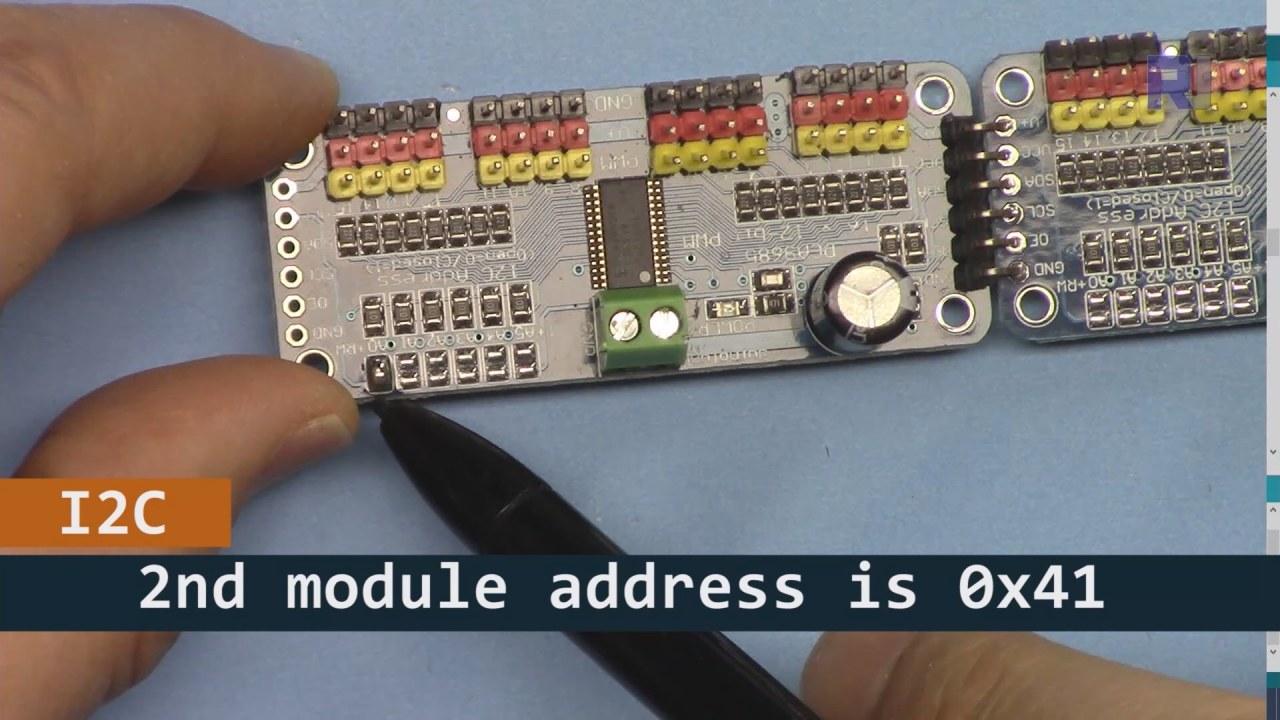
Come mostrato nell'immagine sopra, devi saldare i pin indicati sulla scheda 2, che devono essere diversi da quelli della scheda 1. In questo modo avremo indirizzi i2C diversi e potrai controllare la scheda.
Esempi di codice e guida passo-passo
Diamo un'occhiata alla parte di configurazione del codice che inizializza i moduli PCA9685. Qui definiamo gli indirizzi per ciascuna scheda:
Adafruit_PWMServoDriver board1 = Adafruit_PWMServoDriver(0x40);
Adafruit_PWMServoDriver board2 = Adafruit_PWMServoDriver(0x41);
In questo estratto, creiamo istanze del driver PCA9685 per entrambe le schede, specificando i rispettivi indirizzi I2C. Questa configurazione è fondamentale per garantire che il nostro Arduino possa comunicare con entrambi i moduli.
Ilsetup()la funzione inizializza le schede e imposta la frequenza PWM:
void setup() {
  Serial.begin(9600);
  board1.begin();
  board2.begin();
  board1.setPWMFreq(60);  // Analog servos run at ~60 Hz updates
  board2.setPWMFreq(60);
}
Qui iniziamo la comunicazione seriale e impostiamo entrambe le schede per operare a una frequenza di 60 Hz, che è standard per la maggior parte dei servomotori. Questo garantisce un funzionamento fluido mentre controlliamo i servomotori.
Successivamente, esaminiamo la logica di controllo nelloop()funzione:
for(int angle = 0; angle < 181; angle += 10) {
  for(int i = 0; i < 16; i++) {
    board1.setPWM(i, 0, angleToPulse(angle));
    board2.setPWM(i, 0, angleToPulse(angle));
  }
}
Questo ciclo incrementa l'angolo da 0 a 180 gradi in passi di 10. Per ogni angolo, imposta il segnale PWM per tutti i servocomandi su entrambe le schede, permettendo loro di muoversi all'unisono da 0 a 180 gradi e viceversa.angleToPulse()La funzione converte l'angolo nella corrispondente larghezza dell'impulso per i servocomandi.
Dimostrazione / Cosa Aspettarsi
Una volta che tutto è cablato e il codice è caricato, dovresti vedere tutti e 32 i servi muoversi insieme, passando attraverso gli angoli senza intoppi. Se premi il pulsante, cambierà lo stato di tutti i servi tra acceso e spento (nel video a :00). Fai attenzione alla polarità invertita e assicurati che i tuoi servi siano stati progettati per la corrente fornita per evitare il surriscaldamento.
Timestamp video
- 00:00 Inizio
- 01:18 Introduzione
- 04:30 Preparazione ai moduli
- 07:56 spiegazione del cablaggio
- 10:25 Requisito di potenza
- 11:33 Codice Spiegato
- 19:54 Codice 2 Spiegato (8 servomotori insieme su ogni scheda)
- 20:40 Dimostrazione 8 controllo servo insieme
- 21:55 Dimostrazione Tutti e 32 i servo si muovono insieme
- 22:28 Codice per il pulsante di pressione spiegato
- 24:43 Spiegazione del cablaggio per il pulsante di pressione
- 25:12 Dimostrazione dell'uso dell'interruttore a pulsante
Immagini


Questo tutorial è parte di: Controllo di 16 o 32 servomotori con PCA9685
- Codice Arduino e video per il controller per servomotori PCA9685 a 16 canali e 12 bit V1
- Controlla 16 Motori Servo utilizzando un modulo PCA9685 e sketch Arduino V2 #1: Uno per uno
- Controllo di 16 servomotori utilizzando un modulo PCA9685 e uno sketch Arduino V2: Controllo individuale dei servomotori
- Controlling 16 Servo Motors Using a PCA9685 Module and Arduino V2 Sketch #3: All Servos Together
- Controllare un servomotore da 32 utilizzando un modulo PCA9685 e un ESP32 V4
- Controlla 32 servomotori tramite Wi-Fi utilizzando ESP32 e PCA9685 tramite desktop o telefono cellulare V5
/*
 * Original source: https://github.com/adafruit/Adafruit-PWM-Servo-Driver-Library
 *
 * This is the Arduino code to use two PCA6985 boards and control 32 servo motor
 *
 * This is V3 Video on PCA9685: https://youtu.be/6P21wG7N6t4
 *  get this code and wiring from for this video:  http://robojax.com/RJT249
to learn better: watch the video for details (V1) and demo http://youtu.be/y8X9X10Tn1k


 * Written/updated by Ahmad Shamshiri for Robojax Video channel www.Robojax.com
 * Date: Dec 15, 2019, in Ajax, Ontario, Canada

 * Watch video for this code:
 *
 * Related Videos
V5 video of PCA9685 32 Servo with ESP32 with WiFi https://youtu.be/bvqfv-FrrLM
V4 video of PCA9685 32 Servo with ESP32 (no WiFi): https://youtu.be/JFdXB8Za5Os
V3 video of PCA9685 how to control 32 Servo motors https://youtu.be/6P21wG7N6t4
V2 Video of PCA9685 3 different ways to control Servo motors: https://youtu.be/bal2STaoQ1M
V1 Video introduction to PCA9685 to control 16 Servo  https://youtu.be/y8X9X10Tn1k
 * Disclaimer: this code is "AS IS" and for educational purpose only.


or make donation using PayPal http://robojax.com/L/?id=64

 *  * This code is "AS IS" without warranty or liability. Free to be used as long as you keep this note intact.*
 * This code has been download from Robojax.com
    This program is free software: you can redistribute it and/or modify
    it under the terms of the GNU General Public License as published by
    the Free Software Foundation, either version 3 of the License, or
    (at your option) any later version.

    This program is distributed in the hope that it will be useful,
    but WITHOUT ANY WARRANTY; without even the implied warranty of
    MERCHANTABILITY or FITNESS FOR A PARTICULAR PURPOSE.  See the
    GNU General Public License for more details.

    You should have received a copy of the GNU General Public License
    along with this program.  If not, see <https://www.gnu.org/licenses/>.
 */
#include <Wire.h>
#include <Adafruit_PWMServoDriver.h>

// called this way, it uses the default address 0x40
Adafruit_PWMServoDriver board1 = Adafruit_PWMServoDriver(0x40);
Adafruit_PWMServoDriver board2 = Adafruit_PWMServoDriver(0x41);

// Depending on your servo make, the pulse width min and max may vary, you
// want these to be as small/large as possible without hitting the hard stop
// for max range. You'll have to tweak them as necessary to match the servos you
// have!
// Watch video V1 to understand the two lines below: http://youtu.be/y8X9X10Tn1k
#define SERVOMIN  125 // this is the 'minimum' pulse length count (out of 4096)
#define SERVOMAX  575 // this is the 'maximum' pulse length count (out of 4096)


int servoNumber = 0;

void setup() {
  Serial.begin(9600);
  Serial.println("16 channel Servo test!");

  board1.begin();
  board2.begin();
  board1.setPWMFreq(60);  // Analog servos run at ~60 Hz updates
  board2.setPWMFreq(60);
  //yield();
}

// the code inside loop() has been updated by Robojax
void loop() {


    for( int angle =0; angle<181; angle +=10){
      for(int i=0; i<16; i++)
        {
            board2.setPWM(i, 0, angleToPulse(angle) );
            board1.setPWM(i, 0, angleToPulse(angle) );
        }
    }

// robojax PCA9865 16 channel Servo control
  delay(100);

}

/*
 * angleToPulse(int ang)
 * gets angle in degree and returns the pulse width
 * also prints the value on seial monitor
 * written by Ahmad Nejrabi for Robojax, Robojax.com
 */
int angleToPulse(int ang){
   int pulse = map(ang,0, 180, SERVOMIN,SERVOMAX);// map angle of 0 to 180 to Servo min and Servo max
   Serial.print("Angle: ");Serial.print(ang);
   Serial.print(" pulse: ");Serial.println(pulse);
   return pulse;
}/*
* Original source: https://github.com/adafruit/Adafruit-PWM-Servo-Driver-Library
*
* This is the Arduino code for two PAC6985 board to control 16 servo on each board
* total 32 servos using I2C communication
* get this code and wiring from for this video (V3): http://robojax.com/RJT249
watch the video for details (V2) and demo https://youtu.be/6P21wG7N6t4
* watch the video for details (V1) and demo http://youtu.be/y8X9X10Tn1k
* This code is #3 for V2 Video Watch the video :
* I have got 3 codes as follow:https://youtu.be/bal2STaoQ1M
*
#1-Arduino Code to run one by one all servos from 0 to 180°
#2-Arduino Code to control specific servos with specific angle
#3-Arduino Code to run 2 or all servos at together
* Written/updated by Ahmad Shamshiri for Robojax Video channel www.Robojax.com
* Date: Dec 16, 2017, in Ajax, Ontario, Canada
* Permission granted to share this code given that this
* note is kept with the code.
* Disclaimer: this code is "AS IS" and for educational purpose only.
* this code has been downloaded from http://robojax.com/
or make donation using PayPal http://robojax.com/L/?id=64
* * This code is "AS IS" without warranty or liability. Free to be used as long as you keep this note intact.*
* This code has been download from Robojax.com
This program is free software: you can redistribute it and/or modify
it under the terms of the GNU General Public License as published by
the Free Software Foundation, either version 3 of the License, or
(at your option) any later version.
This program is distributed in the hope that it will be useful,
but WITHOUT ANY WARRANTY; without even the implied warranty of
MERCHANTABILITY or FITNESS FOR A PARTICULAR PURPOSE. See the
GNU General Public License for more details.
You should have received a copy of the GNU General Public License
along with this program. If not, see <https://www.gnu.org/licenses/>.
*/
#include <Wire.h>
#include <Adafruit_PWMServoDriver.h>
// called this way, it uses the default address 0x40
Adafruit_PWMServoDriver board1 = Adafruit_PWMServoDriver(0x40);
Adafruit_PWMServoDriver board2 = Adafruit_PWMServoDriver(0x41);
// Depending on your servo make, the pulse width min and max may vary, you
// want these to be as small/large as possible without hitting the hard stop
// for max range. You'll have to tweak them as necessary to match the servos you
// have!
// Watch video V1 to understand the two lines below: http://youtu.be/y8X9X10Tn1k
#define SERVOMIN 125 // this is the 'minimum' pulse length count (out of 4096)
#define SERVOMAX 575 // this is the 'maximum' pulse length count (out of 4096)
int servoNumber = 0;
void setup() {
Serial.begin(9600);
Serial.println("16 channel Servo test!");
board1.begin();
board2.begin();
board1.setPWMFreq(60); // Analog servos run at ~60 Hz updates
board2.setPWMFreq(60);
//yield();
}
// the code inside loop() has been updated by Robojax
void loop() {
for( int angle =0; angle<181; angle +=10){
for(int i=0; i<8; i++)
{
board2.setPWM(i, 0, angleToPulse(angle) );
board1.setPWM(i, 0, angleToPulse(angle) );
}
}
for( int angle =0; angle<181; angle +=30){
for(int i=8; i<16; i++)
{
board2.setPWM(i, 0, angleToPulse(angle) );
board1.setPWM(i, 0, angleToPulse(angle) );
}
}
// robojax PCA9865 16 channel Servo control
delay(100);
}
/*
* angleToPulse(int ang)
* gets angle in degree and returns the pulse width
* also prints the value on serial monitor
* written by Ahmad Shamshiri for Robojax, Robojax.com
*/
int angleToPulse(int ang){
int pulse = map(ang,0, 180, SERVOMIN,SERVOMAX);// map angle of 0 to 180 to Servo min and Servo max
Serial.print("Angle: ");Serial.print(ang);
Serial.print(" pulse: ");Serial.println(pulse);
return pulse;
}
 /* Original source: https://github.com/adafruit/Adafruit-PWM-Servo-Driver-Library
 *
 * This is the Arduino code for two PAC6985 board  and push button

 * total 32 servos using I2C communication
 * get this code and wiring from for this video (V3):  http://robojax.com/RJT249


 * watch the video for details (V1) and demo http://youtu.be/y8X9X10Tn1k
 *  This code is #3 for V2 Video Watch the video :
 *  I have got 3 codes as follow:https://youtu.be/bal2STaoQ1M
 *
   #1-Arduino Code to run one by one all servos from 0 to 180°
   #2-Arduino Code to control specific servos with specific angle
   #3-Arduino Code to run 2 or all servos at together

 * Written/updated by Ahmad Shamshiri for Robojax Video channel www.Robojax.com
 * Date: Dec 16, 2017, in Ajax, Ontario, Canada
 * Permission granted to share this code given that this
 * note is kept with the code.
 * Disclaimer: this code is "AS IS" and for educational purpose only.


 *  * This code is "AS IS" without warranty or liability. Free to be used as long as you keep this note intact.*
 * This code has been download from Robojax.com
    This program is free software: you can redistribute it and/or modify
    it under the terms of the GNU General Public License as published by
    the Free Software Foundation, either version 3 of the License, or
    (at your option) any later version.

    This program is distributed in the hope that it will be useful,
    but WITHOUT ANY WARRANTY; without even the implied warranty of
    MERCHANTABILITY or FITNESS FOR A PARTICULAR PURPOSE.  See the
    GNU General Public License for more details.

    You should have received a copy of the GNU General Public License
    along with this program.  If not, see <https://www.gnu.org/licenses/>.
 */
#include <Wire.h>
#include <Adafruit_PWMServoDriver.h>

// called this way, it uses the default address 0x40
Adafruit_PWMServoDriver board1 = Adafruit_PWMServoDriver(0x40);
Adafruit_PWMServoDriver board2 = Adafruit_PWMServoDriver(0x41);

// Depending on your servo make, the pulse width min and max may vary, you
// want these to be as small/large as possible without hitting the hard stop
// for max range. You'll have to tweak them as necessary to match the servos you
// have!
// Watch video V1 to understand the two lines below: http://youtu.be/y8X9X10Tn1k
#define SERVOMIN  125 // this is the 'minimum' pulse length count (out of 4096)
#define SERVOMAX  575 // this is the 'maximum' pulse length count (out of 4096)

#define PUSH_BUTTON_PIN 2
#define OE_PIN 8

int boardState= LOW;
int showDebug=0;
int angle = 0;
int angleStep =10;

void setup() {
  Serial.begin(9600);
  Serial.println("16 channel Servo test!");

  board1.begin();
  board2.begin();
  board1.setPWMFreq(60);  // Analog servos run at ~60 Hz updates
  board2.setPWMFreq(60);

  pinMode(PUSH_BUTTON_PIN,INPUT_PULLUP);
  pinMode(OE_PIN, OUTPUT);
  digitalWrite(OE_PIN,LOW);//turn module ON

}

// the code inside loop() has been updated by Robojax
void loop() {
   if(digitalRead(PUSH_BUTTON_PIN) == LOW)
   {
    boardState = 1-boardState;
    Serial.println("push button pressed");
    delay(200); // give the finger time
   }
 digitalWrite(OE_PIN, boardState);
    for( int angle =0; angle<181; angle +=angleStep){
      delay(50);
      for(int i=0; i<16; i++)
        {
          board1.setPWM(i, 0, angleToPulse(angle) );
          board2.setPWM(i, 0, angleToPulse(angle) );
        }
    }

// robojax PCA9865 16 channel Servo control
  delay(100);

}

/*
 * angleToPulse(int ang)
 * gets angle in degree and returns the pulse width
 * also prints the value on serial monitor
 * written by Ahmad Shamshiri for Robojax, Robojax.com
 */
int angleToPulse(int ang){
   int pulse = map(ang,0, 180, SERVOMIN,SERVOMAX);// map angle of 0 to 180 to Servo min and Servo max
  if(showDebug)
  {
   Serial.print("Angle: ");Serial.print(ang);
   Serial.print(" pulse: ");Serial.println(pulse);
  }
   return pulse;
}

/*
 * updateState()
 * @brief reads push buttons and updates values
 * @param none
 * @return no return
 * Written by Ahmad Shamshiri for robojax.com
 * on Nov 01, 2019 at 18:10 in Ajax, Ontario, Canada
 */
void updateState()
{
   if(digitalRead(PUSH_BUTTON_PIN) == LOW)
   {
    boardState = 1-boardState;
    Serial.println("push button pressed");
    delay(200); // give the finger time
   }
   digitalWrite(OE_PIN, boardState);
}//updateState end
Cose di cui potresti avere bisogno
-
AmazonAcquista PCA9685 da Amazonamzn.to
-
eBayAcquista PCA9685 su eBayebay.us
-
AliExpressAcquista PCA9685 da AliExpresss.click.aliexpress.com
-
BanggoodAcquista PCA9685 da Bangoodbanggood.com
Risorse e riferimenti
Nessuna risorsa ancora.
File📁
Librerie Arduino (zip)
-
Adafruit-PWM-Servo-Driver-Library-master
Adafruit-PWM-Servo-Driver-Library-master.zip0.02 MB