Ce tutoriel fait partie de: Commande de 16 ou 32 servomoteurs avec PCA9685
Cette collection de tutoriels vidéo vous aide à contrôler 32 servomoteurs ou plus à l'aide d'Arduino UNO, Nano, Mini ou ESP32. Tous les codes sont fournis.

Contrôler un moteur servo 32 en utilisant un module PCA9685 et un croquis Arduino V3 #1 : Tous les servos ensemble
Dans ce tutoriel, nous apprendrons comment contrôler 32 servomoteurs en utilisant deux modules pilotes PWM PCA9685 connectés à un Arduino. Le PCA9685 est un module polyvalent qui permet de contrôler facilement plusieurs servos via une communication I2C. À la fin de ce projet, vous serez en mesure de faire bouger tous les 32 servos à l'unisson avec une configuration simple.

Nous allons également mettre en place un bouton poussoir qui pourra allumer ou éteindre tous les servos simultanément. Cette fonctionnalité ajoute une couche supplémentaire de contrôle et rend le projet plus interactif. Pour une compréhension visuelle de la configuration et du code, assurez-vous de consulter la vidéo d'accompagnement (dans la vidéo à 00:00).
Matériel expliqué
Le composant clé de ce projet est le module PCA9685, qui fournit 16 canaux pour les signaux PWM. Ce module utilise la communication I2C, avec les broches SDA et SCL qui gèrent la transmission de données. Chaque PCA9685 peut contrôler jusqu'à 16 servos, mais en cascade deux modules, nous pouvons contrôler 32 servos simultanément.
L'Arduino sert de contrôleur, envoyant des commandes aux modules PCA9685. Chaque moteur servo sera connecté à l'une des broches de sortie du PCA9685, permettant un contrôle précis de leurs positions. Une alimentation externe adéquate est cruciale, car les servos peuvent tirer un courant significatif.
Détails de la fiche technique
| Fabricant | Adafruit |
|---|---|
| Numéro de pièce | PCA9685 |
| Tension logique/IO | 3,3 V à 5,5 V |
| Tension d'alimentation | 5 V (externe pour servomoteurs) |
| Courant de sortie (par canal) | ~20 mA |
| Courant de crête (par canal) | ~25 mA |
| Directives de fréquence PWM | 40 Hz à 1000 Hz |
| Seuils de logique d'entrée | 0,3 V (bas), 0,7 V (haut) |
| Chute de tension / RDS(on)/ saturation | ~0,5 V |
| Limites thermiques | Température de fonctionnement : -40°C à +85°C |
| Paquet | TSSOP à 16 broches |
| Notes / variantes | Peut enchaîner plusieurs tableaux pour un contrôle élargi |
- Assurez-vous d'une alimentation appropriée pour éviter le blocage du servomoteur.
- Utilisez une alimentation externe pour les servos ; l'Arduino ne peut pas fournir un courant suffisant.
- Connectez le pôle de référence du PCA9685 à la masse de l'Arduino.
- Maintenez la broche OE à la masse pour activer le module.
- Notez l'adresse I2C pour chaque module ; la valeur par défaut est 0x40 pour le premier et 0x41 pour le second.
Instructions de câblage

Pour câbler les modules PCA9685 et les servomoteurs, commencez par connecter l'alimentation et la masse. Connectez la broche VCC du PCA9685 à la broche 5V de l'Arduino et connectez la broche de masse à la GND de l'Arduino. Pour l'alimentation du servomoteur, utilisez une alimentation externe connectée à la broche V+ du PCA9685.
Ensuite, connectez les broches SDA et SCL des modules PCA9685 aux broches A4 et A5 de l'Arduino, respectivement. Si vous utilisez plusieurs modules PCA9685, connectez-les en série. Assurez-vous que la broche OE est connectée à la terre pour activer les sorties. Enfin, connectez le fil de signal de chaque servo aux broches de sortie PWM respectives sur le PCA9685 (0-15 pour le premier module et 16-31 pour le deuxième module).
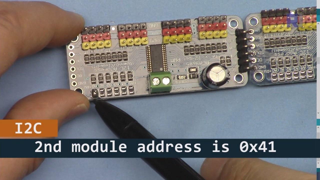
Comme montré dans l'image ci-dessus, vous devez souder les broches indiquées sur la carte 2 et elles doivent être différentes de celles de la carte 1. De cette façon, nous aurons une adresse i2C différente et vous pourrez contrôler la carte.
Exemples de code et guide étape par étape
Jetons un œil à la partie configuration du code qui initialise les modules PCA9685. C'est ici que nous définissons les adresses pour chaque carte :
Adafruit_PWMServoDriver board1 = Adafruit_PWMServoDriver(0x40);
Adafruit_PWMServoDriver board2 = Adafruit_PWMServoDriver(0x41);
Dans cet extrait, nous créons des instances du pilote PCA9685 pour les deux cartes, en spécifiant leurs adresses I2C. Cette configuration est cruciale pour garantir que notre Arduino puisse communiquer avec les deux modules.
Lesetup()la fonction initialise les cartes et définit la fréquence PWM :
void setup() {
  Serial.begin(9600);
  board1.begin();
  board2.begin();
  board1.setPWMFreq(60);  // Analog servos run at ~60 Hz updates
  board2.setPWMFreq(60);
}
Ici, nous démarrons la communication série et réglons les deux cartes pour fonctionner à une fréquence de 60 Hz, ce qui est standard pour la plupart des servos. Cela garantit un fonctionnement fluide lorsque nous contrôlons les servos.
Ensuite, examinons la logique de contrôle dans leloop()function:
for(int angle = 0; angle < 181; angle += 10) {
  for(int i = 0; i < 16; i++) {
    board1.setPWM(i, 0, angleToPulse(angle));
    board2.setPWM(i, 0, angleToPulse(angle));
  }
}
Cette boucle incrémente l'angle de 0 à 180 degrés par pas de 10. Pour chaque angle, elle définit le signal PWM pour tous les servos sur les deux cartes, leur permettant de se déplacer à l'unisson de 0 à 180 degrés et retour.angleToPulse()la fonction convertit l'angle en largeur d'impulsion correspondante pour les servos.
Démonstration / À quoi s'attendre
Une fois que tout est câblé et que le code est téléchargé, vous devriez voir les 32 servos se déplacer ensemble, parcourant les angles en douceur. Si vous appuyez sur le bouton-poussoir, il va changer l'état de tous les servos entre marche et arrêt (dans la vidéo à 00:00). Faites attention à la polarité inversée et assurez-vous que vos servos sont capables de supporter le courant fourni pour éviter la surchauffe.
Timestamps vidéo
- 00:00 Début
- 01:18 Introduction
- 04:30 Préparation des modules
- 07:56 explication du câblage
- 10:25 Exigence en puissance
- 11:33 Code Expliqué
- 19:54 Code 2 Expliqué (8 servos ensemble sur chaque carte)
- 20:40 Démonstration 8 contrôle de servo ensemble
- 21:55 Démonstration Tous les 32 servo-moteurs se déplacent ensemble
- 22:28 Code pour le bouton poussoir expliqué
- 24:43 Explication du câblage pour le bouton-poussoir
- 25:12 Démonstration de l'utilisation d'un interrupteur à bouton-poussoir
Images


Ce tutoriel fait partie de: Commande de 16 ou 32 servomoteurs avec PCA9685
- Code Arduino et vidéo pour le contrôleur de servomoteurs PCA9685 16 canaux 12 bits V1
- Contrôlez 16 servomoteurs à l'aide d'un module PCA9685 et du croquis Arduino V2 #1 : Un par un
- Contrôler 16 moteurs servo à l'aide d'un module PCA9685 et d'un croquis Arduino V2 : Contrôle individuel des servos
- Controlling 16 Servo Motors Using a PCA9685 Module and Arduino V2 Sketch #3: All Servos Together
- Contrôler un moteur servo 32 à l'aide d'un module PCA9685 et d'un ESP32 V4
- Contrôlez 32 servomoteurs via Wi-Fi en utilisant ESP32 et PCA9685 depuis un ordinateur de bureau ou un téléphone mobile V5
/*
 * Original source: https://github.com/adafruit/Adafruit-PWM-Servo-Driver-Library
 *
 * This is the Arduino code to use two PCA6985 boards and control 32 servo motor
 *
 * This is V3 Video on PCA9685: https://youtu.be/6P21wG7N6t4
 *  get this code and wiring from for this video:  http://robojax.com/RJT249
to learn better: watch the video for details (V1) and demo http://youtu.be/y8X9X10Tn1k


 * Written/updated by Ahmad Shamshiri for Robojax Video channel www.Robojax.com
 * Date: Dec 15, 2019, in Ajax, Ontario, Canada

 * Watch video for this code:
 *
 * Related Videos
V5 video of PCA9685 32 Servo with ESP32 with WiFi https://youtu.be/bvqfv-FrrLM
V4 video of PCA9685 32 Servo with ESP32 (no WiFi): https://youtu.be/JFdXB8Za5Os
V3 video of PCA9685 how to control 32 Servo motors https://youtu.be/6P21wG7N6t4
V2 Video of PCA9685 3 different ways to control Servo motors: https://youtu.be/bal2STaoQ1M
V1 Video introduction to PCA9685 to control 16 Servo  https://youtu.be/y8X9X10Tn1k
 * Disclaimer: this code is "AS IS" and for educational purpose only.


or make donation using PayPal http://robojax.com/L/?id=64

 *  * This code is "AS IS" without warranty or liability. Free to be used as long as you keep this note intact.*
 * This code has been download from Robojax.com
    This program is free software: you can redistribute it and/or modify
    it under the terms of the GNU General Public License as published by
    the Free Software Foundation, either version 3 of the License, or
    (at your option) any later version.

    This program is distributed in the hope that it will be useful,
    but WITHOUT ANY WARRANTY; without even the implied warranty of
    MERCHANTABILITY or FITNESS FOR A PARTICULAR PURPOSE.  See the
    GNU General Public License for more details.

    You should have received a copy of the GNU General Public License
    along with this program.  If not, see <https://www.gnu.org/licenses/>.
 */
#include <Wire.h>
#include <Adafruit_PWMServoDriver.h>

// called this way, it uses the default address 0x40
Adafruit_PWMServoDriver board1 = Adafruit_PWMServoDriver(0x40);
Adafruit_PWMServoDriver board2 = Adafruit_PWMServoDriver(0x41);

// Depending on your servo make, the pulse width min and max may vary, you
// want these to be as small/large as possible without hitting the hard stop
// for max range. You'll have to tweak them as necessary to match the servos you
// have!
// Watch video V1 to understand the two lines below: http://youtu.be/y8X9X10Tn1k
#define SERVOMIN  125 // this is the 'minimum' pulse length count (out of 4096)
#define SERVOMAX  575 // this is the 'maximum' pulse length count (out of 4096)


int servoNumber = 0;

void setup() {
  Serial.begin(9600);
  Serial.println("16 channel Servo test!");

  board1.begin();
  board2.begin();
  board1.setPWMFreq(60);  // Analog servos run at ~60 Hz updates
  board2.setPWMFreq(60);
  //yield();
}

// the code inside loop() has been updated by Robojax
void loop() {


    for( int angle =0; angle<181; angle +=10){
      for(int i=0; i<16; i++)
        {
            board2.setPWM(i, 0, angleToPulse(angle) );
            board1.setPWM(i, 0, angleToPulse(angle) );
        }
    }

// robojax PCA9865 16 channel Servo control
  delay(100);

}

/*
 * angleToPulse(int ang)
 * gets angle in degree and returns the pulse width
 * also prints the value on seial monitor
 * written by Ahmad Nejrabi for Robojax, Robojax.com
 */
int angleToPulse(int ang){
   int pulse = map(ang,0, 180, SERVOMIN,SERVOMAX);// map angle of 0 to 180 to Servo min and Servo max
   Serial.print("Angle: ");Serial.print(ang);
   Serial.print(" pulse: ");Serial.println(pulse);
   return pulse;
}/*
* Original source: https://github.com/adafruit/Adafruit-PWM-Servo-Driver-Library
*
* This is the Arduino code for two PAC6985 board to control 16 servo on each board
* total 32 servos using I2C communication
* get this code and wiring from for this video (V3): http://robojax.com/RJT249
watch the video for details (V2) and demo https://youtu.be/6P21wG7N6t4
* watch the video for details (V1) and demo http://youtu.be/y8X9X10Tn1k
* This code is #3 for V2 Video Watch the video :
* I have got 3 codes as follow:https://youtu.be/bal2STaoQ1M
*
#1-Arduino Code to run one by one all servos from 0 to 180°
#2-Arduino Code to control specific servos with specific angle
#3-Arduino Code to run 2 or all servos at together
* Written/updated by Ahmad Shamshiri for Robojax Video channel www.Robojax.com
* Date: Dec 16, 2017, in Ajax, Ontario, Canada
* Permission granted to share this code given that this
* note is kept with the code.
* Disclaimer: this code is "AS IS" and for educational purpose only.
* this code has been downloaded from http://robojax.com/
or make donation using PayPal http://robojax.com/L/?id=64
* * This code is "AS IS" without warranty or liability. Free to be used as long as you keep this note intact.*
* This code has been download from Robojax.com
This program is free software: you can redistribute it and/or modify
it under the terms of the GNU General Public License as published by
the Free Software Foundation, either version 3 of the License, or
(at your option) any later version.
This program is distributed in the hope that it will be useful,
but WITHOUT ANY WARRANTY; without even the implied warranty of
MERCHANTABILITY or FITNESS FOR A PARTICULAR PURPOSE. See the
GNU General Public License for more details.
You should have received a copy of the GNU General Public License
along with this program. If not, see <https://www.gnu.org/licenses/>.
*/
#include <Wire.h>
#include <Adafruit_PWMServoDriver.h>
// called this way, it uses the default address 0x40
Adafruit_PWMServoDriver board1 = Adafruit_PWMServoDriver(0x40);
Adafruit_PWMServoDriver board2 = Adafruit_PWMServoDriver(0x41);
// Depending on your servo make, the pulse width min and max may vary, you
// want these to be as small/large as possible without hitting the hard stop
// for max range. You'll have to tweak them as necessary to match the servos you
// have!
// Watch video V1 to understand the two lines below: http://youtu.be/y8X9X10Tn1k
#define SERVOMIN 125 // this is the 'minimum' pulse length count (out of 4096)
#define SERVOMAX 575 // this is the 'maximum' pulse length count (out of 4096)
int servoNumber = 0;
void setup() {
Serial.begin(9600);
Serial.println("16 channel Servo test!");
board1.begin();
board2.begin();
board1.setPWMFreq(60); // Analog servos run at ~60 Hz updates
board2.setPWMFreq(60);
//yield();
}
// the code inside loop() has been updated by Robojax
void loop() {
for( int angle =0; angle<181; angle +=10){
for(int i=0; i<8; i++)
{
board2.setPWM(i, 0, angleToPulse(angle) );
board1.setPWM(i, 0, angleToPulse(angle) );
}
}
for( int angle =0; angle<181; angle +=30){
for(int i=8; i<16; i++)
{
board2.setPWM(i, 0, angleToPulse(angle) );
board1.setPWM(i, 0, angleToPulse(angle) );
}
}
// robojax PCA9865 16 channel Servo control
delay(100);
}
/*
* angleToPulse(int ang)
* gets angle in degree and returns the pulse width
* also prints the value on serial monitor
* written by Ahmad Shamshiri for Robojax, Robojax.com
*/
int angleToPulse(int ang){
int pulse = map(ang,0, 180, SERVOMIN,SERVOMAX);// map angle of 0 to 180 to Servo min and Servo max
Serial.print("Angle: ");Serial.print(ang);
Serial.print(" pulse: ");Serial.println(pulse);
return pulse;
}
 /* Original source: https://github.com/adafruit/Adafruit-PWM-Servo-Driver-Library
 *
 * This is the Arduino code for two PAC6985 board  and push button

 * total 32 servos using I2C communication
 * get this code and wiring from for this video (V3):  http://robojax.com/RJT249


 * watch the video for details (V1) and demo http://youtu.be/y8X9X10Tn1k
 *  This code is #3 for V2 Video Watch the video :
 *  I have got 3 codes as follow:https://youtu.be/bal2STaoQ1M
 *
   #1-Arduino Code to run one by one all servos from 0 to 180°
   #2-Arduino Code to control specific servos with specific angle
   #3-Arduino Code to run 2 or all servos at together

 * Written/updated by Ahmad Shamshiri for Robojax Video channel www.Robojax.com
 * Date: Dec 16, 2017, in Ajax, Ontario, Canada
 * Permission granted to share this code given that this
 * note is kept with the code.
 * Disclaimer: this code is "AS IS" and for educational purpose only.


 *  * This code is "AS IS" without warranty or liability. Free to be used as long as you keep this note intact.*
 * This code has been download from Robojax.com
    This program is free software: you can redistribute it and/or modify
    it under the terms of the GNU General Public License as published by
    the Free Software Foundation, either version 3 of the License, or
    (at your option) any later version.

    This program is distributed in the hope that it will be useful,
    but WITHOUT ANY WARRANTY; without even the implied warranty of
    MERCHANTABILITY or FITNESS FOR A PARTICULAR PURPOSE.  See the
    GNU General Public License for more details.

    You should have received a copy of the GNU General Public License
    along with this program.  If not, see <https://www.gnu.org/licenses/>.
 */
#include <Wire.h>
#include <Adafruit_PWMServoDriver.h>

// called this way, it uses the default address 0x40
Adafruit_PWMServoDriver board1 = Adafruit_PWMServoDriver(0x40);
Adafruit_PWMServoDriver board2 = Adafruit_PWMServoDriver(0x41);

// Depending on your servo make, the pulse width min and max may vary, you
// want these to be as small/large as possible without hitting the hard stop
// for max range. You'll have to tweak them as necessary to match the servos you
// have!
// Watch video V1 to understand the two lines below: http://youtu.be/y8X9X10Tn1k
#define SERVOMIN  125 // this is the 'minimum' pulse length count (out of 4096)
#define SERVOMAX  575 // this is the 'maximum' pulse length count (out of 4096)

#define PUSH_BUTTON_PIN 2
#define OE_PIN 8

int boardState= LOW;
int showDebug=0;
int angle = 0;
int angleStep =10;

void setup() {
  Serial.begin(9600);
  Serial.println("16 channel Servo test!");

  board1.begin();
  board2.begin();
  board1.setPWMFreq(60);  // Analog servos run at ~60 Hz updates
  board2.setPWMFreq(60);

  pinMode(PUSH_BUTTON_PIN,INPUT_PULLUP);
  pinMode(OE_PIN, OUTPUT);
  digitalWrite(OE_PIN,LOW);//turn module ON

}

// the code inside loop() has been updated by Robojax
void loop() {
   if(digitalRead(PUSH_BUTTON_PIN) == LOW)
   {
    boardState = 1-boardState;
    Serial.println("push button pressed");
    delay(200); // give the finger time
   }
 digitalWrite(OE_PIN, boardState);
    for( int angle =0; angle<181; angle +=angleStep){
      delay(50);
      for(int i=0; i<16; i++)
        {
          board1.setPWM(i, 0, angleToPulse(angle) );
          board2.setPWM(i, 0, angleToPulse(angle) );
        }
    }

// robojax PCA9865 16 channel Servo control
  delay(100);

}

/*
 * angleToPulse(int ang)
 * gets angle in degree and returns the pulse width
 * also prints the value on serial monitor
 * written by Ahmad Shamshiri for Robojax, Robojax.com
 */
int angleToPulse(int ang){
   int pulse = map(ang,0, 180, SERVOMIN,SERVOMAX);// map angle of 0 to 180 to Servo min and Servo max
  if(showDebug)
  {
   Serial.print("Angle: ");Serial.print(ang);
   Serial.print(" pulse: ");Serial.println(pulse);
  }
   return pulse;
}

/*
 * updateState()
 * @brief reads push buttons and updates values
 * @param none
 * @return no return
 * Written by Ahmad Shamshiri for robojax.com
 * on Nov 01, 2019 at 18:10 in Ajax, Ontario, Canada
 */
void updateState()
{
   if(digitalRead(PUSH_BUTTON_PIN) == LOW)
   {
    boardState = 1-boardState;
    Serial.println("push button pressed");
    delay(200); // give the finger time
   }
   digitalWrite(OE_PIN, boardState);
}//updateState end
Ce dont vous pourriez avoir besoin
-
AmazonAcheter le PCA9685 sur Amazonamzn.to
-
eBayAchetez le PCA9685 sur eBayebay.us
-
AliExpressAcheter PCA9685 sur AliExpresss.click.aliexpress.com
-
BanggoodAcheter PCA9685 sur Bangoodbanggood.com
Ressources et références
Aucune ressource pour le moment.
Fichiers📁
Bibliothèques Arduino (zip)
-
Adafruit-PWM-Servo-Driver-Library-master
Adafruit-PWM-Servo-Driver-Library-master.zip0.02 MB