این آموزش بخشی است از: کنترل سروو موتور ۱۶ یا ۳۲ با PCA9685
این مجموعه آموزش به همراه ویدیو به شما کمک میکند تا ۳۲ یا تعداد بیشتری سروو موتور را با استفاده از آردوینو UNO، نانو، مینی یا ESP32 کنترل کنید. تمام کدها ارائه شده است.

کنترل یک سروو موتور ۳۲ با استفاده از ماجیول PCA9685 و برنامه آردوینو V3 طرح #۱: همه سرووها با هم
در این آموزش، یاد خواهیم گرفت که چگونه ۳۲ سرو موتورها را با استفاده از دو ماجیول درایور PWM PCA9685 که به یک آردوینو متصل هستند، کنترل کنیم. PCA9685 یک ماجیول چندمنظوره است که کنترل آسان چندین سرو را از طریق ارتباط I2C امکانپذیر میسازد. در پایان این پروژه، شما قادر خواهید بود همه ۳۲ سرو را به صورت همزمان با یک تنظیم ساده حرکت دهید.

ما همچنین یک دکمه فشاری را پیادهسازی خواهیم کرد که میتواند تمام سرووها را به طور همزمان روشن یا خاموش کند. این ویژگی یک لایه کنترل اضافی به پروژه اضافه میکند و باعث میشود پروژه تعاملپذیرتر شود. برای درک بصری از تنظیمات و شِفر (کود)، حتما ویدئوی همراه را مشاهده کنید (در ویدیو در ۰۰:۰۰).
توضیح سختافزار
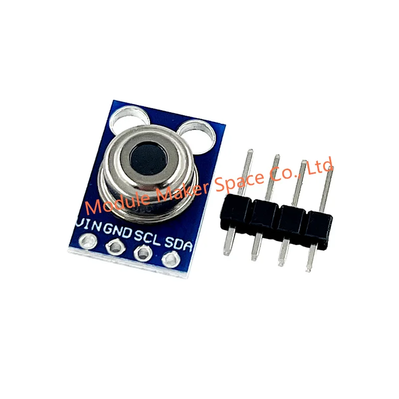
اجزای کلیدی در این پروژه ماجیول PCA9685 است که 16 کانال برای سیگنالهای PWM فراهم میکند. این ماجیول از ارتباط I2C استفاده میکند و پایههای SDA و SCL وظیفه انتقال داده را بر عهده دارند. هر PCA9685 میتواند تا 16 سروو را کنترل کند، اما با اتصال دو ماجیول به هم میتوانیم 32 سروو را بهطور همزمان کنترل کنیم.
آردوینو به عنوان کنترلکننده عمل میکند و دستورات را به ماجیولهای PCA9685 ارسال میکند. هر موتور سروو به یکی از پایههای خروجی روی PCA9685 متصل خواهد شد که کنترل دقیقی بر روی موقعیتهای آنها را امکانپذیر میسازد. تأمین برق خارجی مناسب بسیار مهم است، زیرا سرووها میتوانند جریان قابل توجهی را مصرف کنند.
جزئیات برگه داده
| سازنده | آدافروت |
|---|---|
| شماره قطعه | PCA9685 |
| ولتاژ منطق/ورودی-خروجی | ۳.۳ ولت تا ۵.۵ ولت |
| ولتاژ تامین | ۵ ولت (خارجی برای سرو موتور ها) |
| جریان خروجی (به ازای هر کانال) | ~۲۰ میلی آمپر |
| جریان اوج (به ازای هر کانال) | ~25 میلیآمپر |
| راهنمای فرکانس PWM | ۴۰ هرتز تا ۱۰۰۰ هرتز |
| مراحل آستانه منطق ورودی | ۰.۳ ولت (کم)، ۰.۷ ولت (زیاد) |
| افت ولتاژ / RDS(on)/ اشباع | ~0.5 ولت |
| محدودیتهای حرارتی | دمای عملیاتی: -۴۰ درجه سانتیگراد تا +۸۵ درجه سانتیگراد |
| بسته | 16 پایه TSSOP |
| یادداشتها / تنوعها | میتوان چندین برد را برای کنترل گستردهتر به هم متصل کرد. |
- اطمینان حاصل کنید که منبع تغذیه مناسب است تا از توقف سرور جلوگیری شود.
- از منبع خارجی برای سروها استفاده کنید؛ آردوینو نمیتواند جریان کافی تأمین کند.
- زمین PCA9685 را به زمین آردوینو متصل کنید.
- پایه OE را به زمین متصل نگهدارید تا ماجیول فعال شود.
- آدرس I2C برای هر ماجیول را یادداشت کنید؛ پیشفرض ۰x۴۰ برای اولی و ۰x۴۱ برای دومی است.
دستورالعملهای سیمکشی

برای اتصال ماجیولهای PCA9685 و سرووها، ابتدا با اتصال برق و زمین شروع کنید. پایه VCC را بر روی PCA9685 به پایه ۵ ولت روی آردوینو متصل کنید و پایه زمین را به GND آردوینو متصل کنید. برای تأمین برق سروو، از یک منبع تغذیه خارجی متصل به پایه V+ روی PCA9685 استفاده کنید.
سپس پایههای SDA و SCL ماجیولهای PCA9685 را به پایههای A4 و A5 آردوینو متصل کنید. اگر از چندین ماجیول PCA9685 استفاده میکنید، آنها را به صورت زنجیرهای متصل کنید. اطمینان حاصل کنید که پایه OE به زمین متصل است تا خروجیها فعال شوند. در نهایت، سیم سیگنال هر سرو را به پایههای خروجی PWM مربوطه بر روی PCA9685 متصل کنید (۰-۱۵ برای ماجیول اول و ۱۶-۳۱ برای ماجیول دوم).
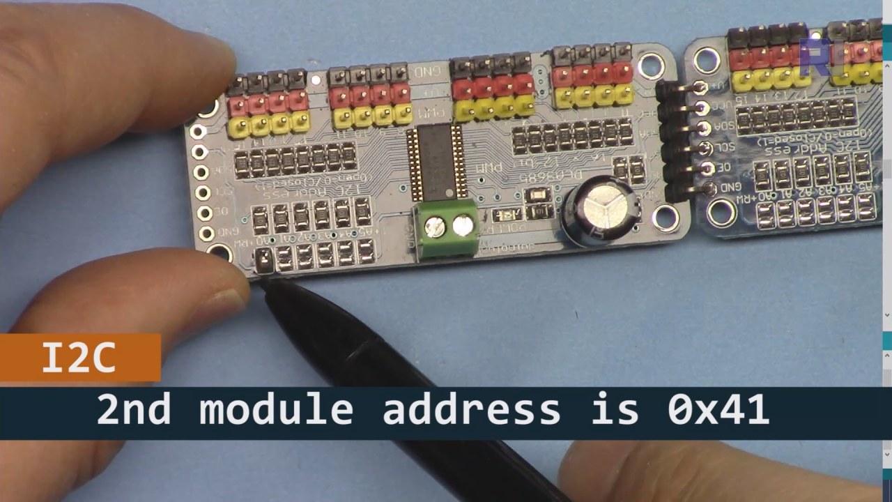
همانطور که در تصویر بالا نشان داده شده است، شما باید پایههای نشاندادهشده را بر روی بورد ۲ لحیم کنید و این باید با بورد ۱ متفاوت باشد. به این ترتیب ما آدرس i2C متفاوتی خواهیم داشت و میتوانید بورد را کنترل کنید.
نمونههای شِفر (کود) و راهنما
بیایید نگاهی به بخش راهاندازی شِفر (کود) بیندازیم که ماجیولهای PCA9685 را初始化 میکند. اینجا جایی است که ما آدرسهای هر برد را تعریف میکنیم:
Adafruit_PWMServoDriver board1 = Adafruit_PWMServoDriver(0x40);
Adafruit_PWMServoDriver board2 = Adafruit_PWMServoDriver(0x41);
در این بخش، ما نمونههایی از درایور PCA9685 را برای هر دو برد ایجاد میکنیم و آدرسهای I2C آنها را مشخص میکنیم. این تنظیمات برای اطمینان از اینکه آردوینو ما میتواند با هر دو ماجیول ارتباط برقرار کند بسیار حیاتی است.
متن:setup()تابع تختهها را راهاندازی میکند و فرکانس PWM را تنظیم میکند:
void setup() {
  Serial.begin(9600);
  board1.begin();
  board2.begin();
  board1.setPWMFreq(60);  // Analog servos run at ~60 Hz updates
  board2.setPWMFreq(60);
}
اینجا، ما ارتباط سریالی را آغاز میکنیم و هر دو برد را به گونهای تنظیم میکنیم که با فرکانس ۶۰ هرتز کار کنند، که استاندارد برای بیشتر سرووهاست. این امر باعث میشود که عملیات به صورت روان انجام شود در حالی که ما بر سرووها کنترل داریم.
بعدی، بیایید به منطق کنترل در بررسی کنیمloop()تابع:
for(int angle = 0; angle < 181; angle += 10) {
  for(int i = 0; i < 16; i++) {
    board1.setPWM(i, 0, angleToPulse(angle));
    board2.setPWM(i, 0, angleToPulse(angle));
  }
}
این حلقه زاویه را از ۰ تا ۱۸۰ درجه در قدمهای ۱۰ افزایش میدهد. برای هر زاویه، سیگنال PWM را برای همه سرورها روی هر دو بورد تنظیم میکند، و به آنها اجازه میدهد که به صورت هماهنگ از ۰ تا ۱۸۰ درجه و بالعکس حرکت کنند.angleToPulse()تابع زاویه را به پهنای پالس مربوط برای سروها تبدیل میکند.
نمایش / چه انتظاری باید داشت
هنگامی که همه چیز متصل شده و شِفر (کود) بارگذاری شد، باید ببینید که تمام ۳۲ سروو به طور همزمان حرکت میکنند و به آرامی از زوایا عبور میکنند. اگر دکمه فشار را فشار دهید، وضعیت همه سرووها بین روشن و خاموش تغییر میکند (در ویدیو در ساعت ۰۰:۰۰). از پلاریته معکوس مراقب باشید و اطمینان حاصل کنید که سرووهای شما برای جریانی که تأمین میشود، مناسب هستند تا از گرم شدن بیش از حد جلوگیری شود.
زمانبندی ویدیو
- ۰۰:۰۰ شروع
- :18 مقدمه
- 04:30 آمادهسازی ماجیولها
- 07:56 توضیح کابلکشی
- نیاز به توان ۱۰:۲۵
- 11:33 توضیح شِفر (کود)
- ۱۹:۵۴ شِفر (کود) ۲ توضیح داده شد (۸ سروو به طور همزمان روی هر برد)
- ۲۰:۴۰ نمایش ۸ کنترل سرو با هم
- ۲۱:۵۵ نمایش تمام ۳۲ سروو به طور همزمان حرکت میکنند
- شِفر (کود) برای توضیح دکمه فشار ۲۲:۲۸
- اتصال برای دکمه فشار توضیح داده شد
- ۲۵:۱۲ نمایش استفاده از سوئیچ دکمهای
تصاویر


این آموزش بخشی از: کنترل سروو موتور ۱۶ یا ۳۲ با PCA9685
- شِفر (کود) آردوینو و ویدیو برای کنترلکننده سروو PCA9685، 16 کاناله، 12 بیتی، V1
- کنترل 16 موتور سروو با استفاده از ماجیول PCA9685 و شِفر (کود) آردوینو V2 نمونه #1: یکی یکی
- کنترل ۲۴ موتور سروو با استفاده از ماجیول PCA9685 و شِفر (کود) Arduino V2: کنترل موتور سروو فردی
- Controlling 16 Servo Motors Using a PCA9685 Module and Arduino V2 Sketch #3: All Servos Together
- کنترل یک موتور سرو 32 با استفاده از ماجیول PCA9685 و یک ESP32 V4
- کنترل ۳۲ سروو از راه Wi-Fi با استفاده از ESP32 و PCA9685 از طریق دسکتاپ یا گوشی موبایل V5
/*
 * Original source: https://github.com/adafruit/Adafruit-PWM-Servo-Driver-Library
 *
 * This is the Arduino code to use two PCA6985 boards and control 32 servo motor
 *
 * This is V3 Video on PCA9685: https://youtu.be/6P21wG7N6t4
 *  get this code and wiring from for this video:  http://robojax.com/RJT249
to learn better: watch the video for details (V1) and demo http://youtu.be/y8X9X10Tn1k


 * Written/updated by Ahmad Shamshiri for Robojax Video channel www.Robojax.com
 * Date: Dec 15, 2019, in Ajax, Ontario, Canada

 * Watch video for this code:
 *
 * Related Videos
V5 video of PCA9685 32 Servo with ESP32 with WiFi https://youtu.be/bvqfv-FrrLM
V4 video of PCA9685 32 Servo with ESP32 (no WiFi): https://youtu.be/JFdXB8Za5Os
V3 video of PCA9685 how to control 32 Servo motors https://youtu.be/6P21wG7N6t4
V2 Video of PCA9685 3 different ways to control Servo motors: https://youtu.be/bal2STaoQ1M
V1 Video introduction to PCA9685 to control 16 Servo  https://youtu.be/y8X9X10Tn1k
 * Disclaimer: this code is "AS IS" and for educational purpose only.


or make donation using PayPal http://robojax.com/L/?id=64

 *  * This code is "AS IS" without warranty or liability. Free to be used as long as you keep this note intact.*
 * This code has been download from Robojax.com
    This program is free software: you can redistribute it and/or modify
    it under the terms of the GNU General Public License as published by
    the Free Software Foundation, either version 3 of the License, or
    (at your option) any later version.

    This program is distributed in the hope that it will be useful,
    but WITHOUT ANY WARRANTY; without even the implied warranty of
    MERCHANTABILITY or FITNESS FOR A PARTICULAR PURPOSE.  See the
    GNU General Public License for more details.

    You should have received a copy of the GNU General Public License
    along with this program.  If not, see <https://www.gnu.org/licenses/>.
 */
#include <Wire.h>
#include <Adafruit_PWMServoDriver.h>

// called this way, it uses the default address 0x40
Adafruit_PWMServoDriver board1 = Adafruit_PWMServoDriver(0x40);
Adafruit_PWMServoDriver board2 = Adafruit_PWMServoDriver(0x41);

// Depending on your servo make, the pulse width min and max may vary, you
// want these to be as small/large as possible without hitting the hard stop
// for max range. You'll have to tweak them as necessary to match the servos you
// have!
// Watch video V1 to understand the two lines below: http://youtu.be/y8X9X10Tn1k
#define SERVOMIN  125 // this is the 'minimum' pulse length count (out of 4096)
#define SERVOMAX  575 // this is the 'maximum' pulse length count (out of 4096)


int servoNumber = 0;

void setup() {
  Serial.begin(9600);
  Serial.println("16 channel Servo test!");

  board1.begin();
  board2.begin();
  board1.setPWMFreq(60);  // Analog servos run at ~60 Hz updates
  board2.setPWMFreq(60);
  //yield();
}

// the code inside loop() has been updated by Robojax
void loop() {


    for( int angle =0; angle<181; angle +=10){
      for(int i=0; i<16; i++)
        {
            board2.setPWM(i, 0, angleToPulse(angle) );
            board1.setPWM(i, 0, angleToPulse(angle) );
        }
    }

// robojax PCA9865 16 channel Servo control
  delay(100);

}

/*
 * angleToPulse(int ang)
 * gets angle in degree and returns the pulse width
 * also prints the value on seial monitor
 * written by Ahmad Nejrabi for Robojax, Robojax.com
 */
int angleToPulse(int ang){
   int pulse = map(ang,0, 180, SERVOMIN,SERVOMAX);// map angle of 0 to 180 to Servo min and Servo max
   Serial.print("Angle: ");Serial.print(ang);
   Serial.print(" pulse: ");Serial.println(pulse);
   return pulse;
}/*
* Original source: https://github.com/adafruit/Adafruit-PWM-Servo-Driver-Library
*
* This is the Arduino code for two PAC6985 board to control 16 servo on each board
* total 32 servos using I2C communication
* get this code and wiring from for this video (V3): http://robojax.com/RJT249
watch the video for details (V2) and demo https://youtu.be/6P21wG7N6t4
* watch the video for details (V1) and demo http://youtu.be/y8X9X10Tn1k
* This code is #3 for V2 Video Watch the video :
* I have got 3 codes as follow:https://youtu.be/bal2STaoQ1M
*
#1-Arduino Code to run one by one all servos from 0 to 180°
#2-Arduino Code to control specific servos with specific angle
#3-Arduino Code to run 2 or all servos at together
* Written/updated by Ahmad Shamshiri for Robojax Video channel www.Robojax.com
* Date: Dec 16, 2017, in Ajax, Ontario, Canada
* Permission granted to share this code given that this
* note is kept with the code.
* Disclaimer: this code is "AS IS" and for educational purpose only.
* this code has been downloaded from http://robojax.com/
or make donation using PayPal http://robojax.com/L/?id=64
* * This code is "AS IS" without warranty or liability. Free to be used as long as you keep this note intact.*
* This code has been download from Robojax.com
This program is free software: you can redistribute it and/or modify
it under the terms of the GNU General Public License as published by
the Free Software Foundation, either version 3 of the License, or
(at your option) any later version.
This program is distributed in the hope that it will be useful,
but WITHOUT ANY WARRANTY; without even the implied warranty of
MERCHANTABILITY or FITNESS FOR A PARTICULAR PURPOSE. See the
GNU General Public License for more details.
You should have received a copy of the GNU General Public License
along with this program. If not, see <https://www.gnu.org/licenses/>.
*/
#include <Wire.h>
#include <Adafruit_PWMServoDriver.h>
// called this way, it uses the default address 0x40
Adafruit_PWMServoDriver board1 = Adafruit_PWMServoDriver(0x40);
Adafruit_PWMServoDriver board2 = Adafruit_PWMServoDriver(0x41);
// Depending on your servo make, the pulse width min and max may vary, you
// want these to be as small/large as possible without hitting the hard stop
// for max range. You'll have to tweak them as necessary to match the servos you
// have!
// Watch video V1 to understand the two lines below: http://youtu.be/y8X9X10Tn1k
#define SERVOMIN 125 // this is the 'minimum' pulse length count (out of 4096)
#define SERVOMAX 575 // this is the 'maximum' pulse length count (out of 4096)
int servoNumber = 0;
void setup() {
Serial.begin(9600);
Serial.println("16 channel Servo test!");
board1.begin();
board2.begin();
board1.setPWMFreq(60); // Analog servos run at ~60 Hz updates
board2.setPWMFreq(60);
//yield();
}
// the code inside loop() has been updated by Robojax
void loop() {
for( int angle =0; angle<181; angle +=10){
for(int i=0; i<8; i++)
{
board2.setPWM(i, 0, angleToPulse(angle) );
board1.setPWM(i, 0, angleToPulse(angle) );
}
}
for( int angle =0; angle<181; angle +=30){
for(int i=8; i<16; i++)
{
board2.setPWM(i, 0, angleToPulse(angle) );
board1.setPWM(i, 0, angleToPulse(angle) );
}
}
// robojax PCA9865 16 channel Servo control
delay(100);
}
/*
* angleToPulse(int ang)
* gets angle in degree and returns the pulse width
* also prints the value on serial monitor
* written by Ahmad Shamshiri for Robojax, Robojax.com
*/
int angleToPulse(int ang){
int pulse = map(ang,0, 180, SERVOMIN,SERVOMAX);// map angle of 0 to 180 to Servo min and Servo max
Serial.print("Angle: ");Serial.print(ang);
Serial.print(" pulse: ");Serial.println(pulse);
return pulse;
}
 /* Original source: https://github.com/adafruit/Adafruit-PWM-Servo-Driver-Library
 *
 * This is the Arduino code for two PAC6985 board  and push button

 * total 32 servos using I2C communication
 * get this code and wiring from for this video (V3):  http://robojax.com/RJT249


 * watch the video for details (V1) and demo http://youtu.be/y8X9X10Tn1k
 *  This code is #3 for V2 Video Watch the video :
 *  I have got 3 codes as follow:https://youtu.be/bal2STaoQ1M
 *
   #1-Arduino Code to run one by one all servos from 0 to 180°
   #2-Arduino Code to control specific servos with specific angle
   #3-Arduino Code to run 2 or all servos at together

 * Written/updated by Ahmad Shamshiri for Robojax Video channel www.Robojax.com
 * Date: Dec 16, 2017, in Ajax, Ontario, Canada
 * Permission granted to share this code given that this
 * note is kept with the code.
 * Disclaimer: this code is "AS IS" and for educational purpose only.


 *  * This code is "AS IS" without warranty or liability. Free to be used as long as you keep this note intact.*
 * This code has been download from Robojax.com
    This program is free software: you can redistribute it and/or modify
    it under the terms of the GNU General Public License as published by
    the Free Software Foundation, either version 3 of the License, or
    (at your option) any later version.

    This program is distributed in the hope that it will be useful,
    but WITHOUT ANY WARRANTY; without even the implied warranty of
    MERCHANTABILITY or FITNESS FOR A PARTICULAR PURPOSE.  See the
    GNU General Public License for more details.

    You should have received a copy of the GNU General Public License
    along with this program.  If not, see <https://www.gnu.org/licenses/>.
 */
#include <Wire.h>
#include <Adafruit_PWMServoDriver.h>

// called this way, it uses the default address 0x40
Adafruit_PWMServoDriver board1 = Adafruit_PWMServoDriver(0x40);
Adafruit_PWMServoDriver board2 = Adafruit_PWMServoDriver(0x41);

// Depending on your servo make, the pulse width min and max may vary, you
// want these to be as small/large as possible without hitting the hard stop
// for max range. You'll have to tweak them as necessary to match the servos you
// have!
// Watch video V1 to understand the two lines below: http://youtu.be/y8X9X10Tn1k
#define SERVOMIN  125 // this is the 'minimum' pulse length count (out of 4096)
#define SERVOMAX  575 // this is the 'maximum' pulse length count (out of 4096)

#define PUSH_BUTTON_PIN 2
#define OE_PIN 8

int boardState= LOW;
int showDebug=0;
int angle = 0;
int angleStep =10;

void setup() {
  Serial.begin(9600);
  Serial.println("16 channel Servo test!");

  board1.begin();
  board2.begin();
  board1.setPWMFreq(60);  // Analog servos run at ~60 Hz updates
  board2.setPWMFreq(60);

  pinMode(PUSH_BUTTON_PIN,INPUT_PULLUP);
  pinMode(OE_PIN, OUTPUT);
  digitalWrite(OE_PIN,LOW);//turn module ON

}

// the code inside loop() has been updated by Robojax
void loop() {
   if(digitalRead(PUSH_BUTTON_PIN) == LOW)
   {
    boardState = 1-boardState;
    Serial.println("push button pressed");
    delay(200); // give the finger time
   }
 digitalWrite(OE_PIN, boardState);
    for( int angle =0; angle<181; angle +=angleStep){
      delay(50);
      for(int i=0; i<16; i++)
        {
          board1.setPWM(i, 0, angleToPulse(angle) );
          board2.setPWM(i, 0, angleToPulse(angle) );
        }
    }

// robojax PCA9865 16 channel Servo control
  delay(100);

}

/*
 * angleToPulse(int ang)
 * gets angle in degree and returns the pulse width
 * also prints the value on serial monitor
 * written by Ahmad Shamshiri for Robojax, Robojax.com
 */
int angleToPulse(int ang){
   int pulse = map(ang,0, 180, SERVOMIN,SERVOMAX);// map angle of 0 to 180 to Servo min and Servo max
  if(showDebug)
  {
   Serial.print("Angle: ");Serial.print(ang);
   Serial.print(" pulse: ");Serial.println(pulse);
  }
   return pulse;
}

/*
 * updateState()
 * @brief reads push buttons and updates values
 * @param none
 * @return no return
 * Written by Ahmad Shamshiri for robojax.com
 * on Nov 01, 2019 at 18:10 in Ajax, Ontario, Canada
 */
void updateState()
{
   if(digitalRead(PUSH_BUTTON_PIN) == LOW)
   {
    boardState = 1-boardState;
    Serial.println("push button pressed");
    delay(200); // give the finger time
   }
   digitalWrite(OE_PIN, boardState);
}//updateState end
مواردی که ممکن است به آنها نیاز داشته باشید
-
آمازون
-
ایبیخرید PCA9685 از eBayebay.us
-
علیاکسپرسخرید PCA9685 از علیاکسپرسs.click.aliexpress.com
-
بنگ گودپیش خرید PCA9685 از بانگودbanggood.com
منابع و مراجع
هنوز هیچ منبعی موجود نیست.
فایلها📁
کتابخانههای آردوینو (zip)
-
کتابخانه-درایور-سروو-پیدبلیوام-آدافروت-اصلی
Adafruit-PWM-Servo-Driver-Library-master.zip0.02 MB