Este tutorial es parte de: Control de 16 o 32 servomotores con PCA9685
Esta colección de tutoriales con video te ayuda a controlar 32 o más servomotores con Arduino UNO, Nano, Mini o ESP32. Se proporcionan todos los códigos.

Controlando un motor servo de 32 utilizando un módulo PCA9685 y el sketch de Arduino V3 #1: Todos los servos juntos
En este tutorial, aprenderemos a controlar 32 servomotores utilizando dos módulos controladores PWM PCA9685 conectados a un Arduino. El PCA9685 es un módulo versátil que permite el control fácil de múltiples servos a través de la comunicación I2C. Al final de este proyecto, podrás mover los 32 servos al unísono con una configuración simple.

También implementaremos un botón que puede encender o apagar todos los servos simultáneamente. Esta característica añade una capa adicional de control y hace que el proyecto sea más interactivo. Para una comprensión visual de la configuración y el código, asegúrate de revisar el video acompañante (en el video a las 00:00).
Hardware Explicado
El componente clave en este proyecto es el módulo PCA9685, que proporciona 16 canales para señales PWM. Este módulo utiliza comunicación I2C, con los pines SDA y SCL encargados de la transmisión de datos. Cada PCA9685 puede controlar hasta 16 servos, pero al encadenar dos módulos, podemos controlar 32 servos simultáneamente.
El Arduino sirve como el controlador, enviando comandos a los módulos PCA9685. Cada servo motor estará conectado a uno de los pines de salida en el PCA9685, lo que permite un control preciso sobre sus posiciones. Un suministro de energía externo adecuado es crucial, ya que los servos pueden consumir una corriente significativa.
Detalles de la hoja de datos
| Fabricante | Adafruit |
|---|---|
| Número de parte | PCA9685 |
| Voltaje de lógica/Entrada-Salida | 3.3 V a 5.5 V |
| Tensión de alimentación | 5 V (externo para servos) |
| Corriente de salida (por canal) | ~20 mA |
| Corriente de pico (por canal) | ~25 mA |
| Guía de frecuencia PWM | 40 Hz a 1000 Hz |
| Umbrales de lógica de entrada | 0.3 V (bajo), 0.7 V (alto) |
| Caída de voltaje / RDS(on)/ saturación | ~0.5 V |
| Límites térmicos | Temperatura de funcionamiento: -40°C a +85°C |
| Paquete | TSSOP de 16 pines |
| Notas / variantes | Se pueden encadenar múltiples tableros para un control ampliado. |
- Asegúrese de proporcionar una fuente de alimentación adecuada para evitar el paro del servo.
- Utiliza alimentación externa para los servos; Arduino no puede suministrar suficiente corriente.
- Conecta la tierra del PCA9685 a la tierra del Arduino.
- Mantén el pin OE en tierra para habilitar el módulo.
- Tenga en cuenta la dirección I2C de cada módulo; el valor predeterminado es 0x40 para el primero y 0x41 para el segundo.
Instrucciones de cableado

Para cablear los módulos PCA9685 y los servos, comienza conectando la alimentación y la tierra. Conecta el pin VCC en el PCA9685 al pin de 5V en el Arduino, y conecta el pin de tierra al GND del Arduino. Para la alimentación del servo, utiliza una fuente de alimentación externa conectada al pin V+ en el PCA9685.
A continuación, conecta los pines SDA y SCL de los módulos PCA9685 a los pines A4 y A5 del Arduino, respectivamente. Si estás utilizando múltiples módulos PCA9685, conéctalos en cadena. Asegúrate de que el pin OE esté conectado a tierra para habilitar las salidas. Finalmente, conecta el cable de señal de cada servo a los respectivos pines de salida PWM en el PCA9685 (0-15 para el primer módulo y 16-31 para el segundo módulo).
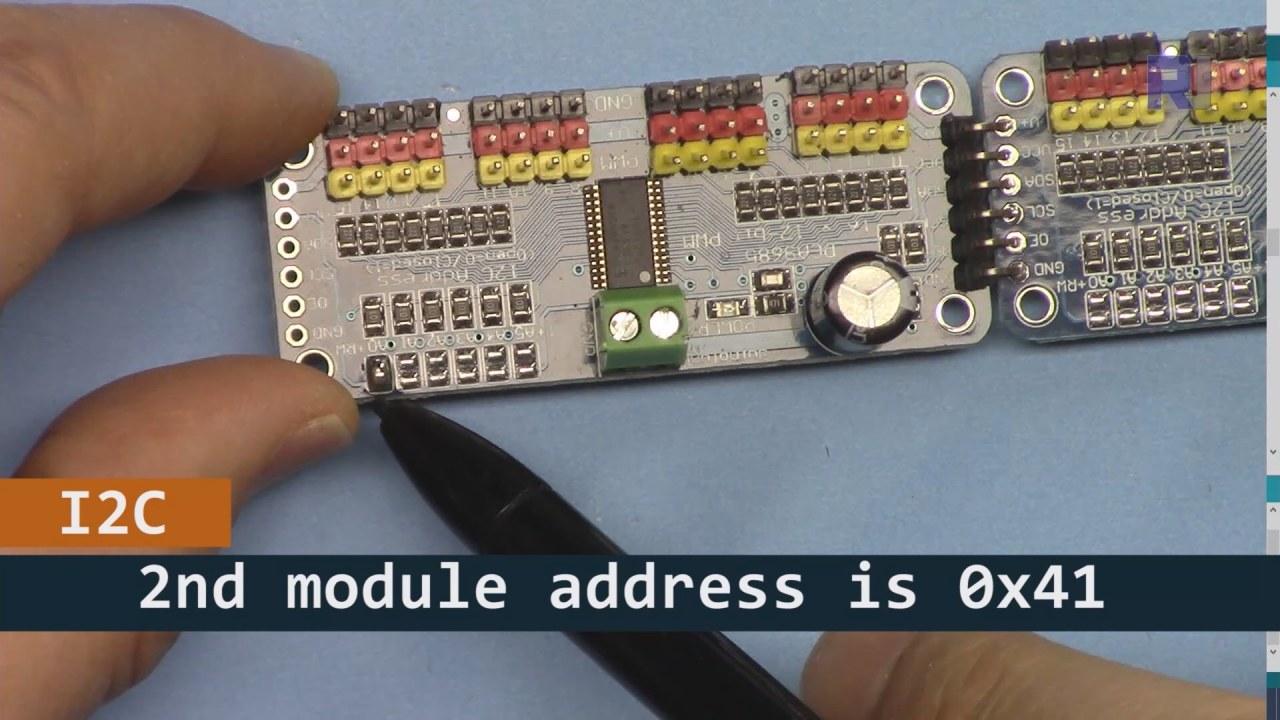
Como se muestra en la imagen de arriba, debes soldar los pines que se muestran en la placa 2 y deben ser diferentes a los de la placa 1. De esta manera, tendremos diferentes direcciones i2C y podrás controlar la placa.
Ejemplos de código y guía paso a paso
Echemos un vistazo a la parte de configuración del código que inicializa los módulos PCA9685. Aquí es donde definimos las direcciones para cada placa:
Adafruit_PWMServoDriver board1 = Adafruit_PWMServoDriver(0x40);
Adafruit_PWMServoDriver board2 = Adafruit_PWMServoDriver(0x41);
En este extracto, creamos instancias del controlador PCA9685 para ambas placas, especificando sus direcciones I2C. Esta configuración es crucial para garantizar que nuestro Arduino pueda comunicarse con ambos módulos.
Elsetup()la función inicializa las placas y establece la frecuencia PWM:
void setup() {
  Serial.begin(9600);
  board1.begin();
  board2.begin();
  board1.setPWMFreq(60);  // Analog servos run at ~60 Hz updates
  board2.setPWMFreq(60);
}
Aquí comenzamos la comunicación serial y configuramos ambas placas para operar a una frecuencia de 60 Hz, que es estándar para la mayoría de los servos. Esto asegura un funcionamiento suave mientras controlamos los servos.
A continuación, veamos la lógica de control en elloop()función:
for(int angle = 0; angle < 181; angle += 10) {
  for(int i = 0; i < 16; i++) {
    board1.setPWM(i, 0, angleToPulse(angle));
    board2.setPWM(i, 0, angleToPulse(angle));
  }
}
Este bucle incrementa el ángulo de 0 a 180 grados en pasos de 10. Para cada ángulo, establece la señal PWM para todos los servos en ambas placas, permitiéndoles moverse al unísono de 0 a 180 grados y de regreso. ElangleToPulse()la función convierte el ángulo a la correspondiente ancho de pulso para los servos.
Demostración / Qué Esperar
Una vez que todo esté cableado y el código esté subido, deberías ver los 32 servos moviéndose juntos, pasando por los ángulos suavemente. Si presionas el botón, cambiará el estado de todos los servos entre encendido y apagado (en el video a las 00:00). Ten cuidado con la polaridad inversa y asegúrate de que tus servos estén clasificados para la corriente suministrada para evitar sobrecalentamientos.
Sellos de tiempo del video
- 00:00 Comienzo
- 01:18 Introducción
- 04:30 Preparándose para los módulos
- 07:56 explicación del cableado
- 10:25 Requisito de potencia
- 11:33 Código explicado
- 19:54 Código 2 Explicado (8 servos juntos en cada placa)
- 20:40 Demostración 8 control de servos juntos
- 21:55 Demostración Todos los 32 servos se mueven juntos
- 22:28 Explicación del código para el botón de pulsar
- 24:43 Explicación del cableado para el botón pulsador
- 25:12 Demostración del uso del interruptor de botón pulsador
Imágenes


Este tutorial es parte de: Control de 16 o 32 servomotores con PCA9685
- Código y vídeo de Arduino para el controlador de servos PCA9685 de 16 canales y 12 bits V1
- Controla 16 servomotores utilizando un módulo PCA9685 y un sketch de Arduino V2 #1: Uno por uno.
- Controlando 16 Servomotores utilizando un módulo PCA9685 y el sketch de Arduino V2: Control individual de servos.
- Controlling 16 Servo Motors Using a PCA9685 Module and Arduino V2 Sketch #3: All Servos Together
- Controlando un motor servo de 32 utilizando un módulo PCA9685 y un ESP32 V4
- Controla 32 servos por Wi-Fi utilizando ESP32 y PCA9685 a través de escritorio o teléfono móvil V5
/*
 * Original source: https://github.com/adafruit/Adafruit-PWM-Servo-Driver-Library
 *
 * This is the Arduino code to use two PCA6985 boards and control 32 servo motor
 *
 * This is V3 Video on PCA9685: https://youtu.be/6P21wG7N6t4
 *  get this code and wiring from for this video:  http://robojax.com/RJT249
to learn better: watch the video for details (V1) and demo http://youtu.be/y8X9X10Tn1k


 * Written/updated by Ahmad Shamshiri for Robojax Video channel www.Robojax.com
 * Date: Dec 15, 2019, in Ajax, Ontario, Canada

 * Watch video for this code:
 *
 * Related Videos
V5 video of PCA9685 32 Servo with ESP32 with WiFi https://youtu.be/bvqfv-FrrLM
V4 video of PCA9685 32 Servo with ESP32 (no WiFi): https://youtu.be/JFdXB8Za5Os
V3 video of PCA9685 how to control 32 Servo motors https://youtu.be/6P21wG7N6t4
V2 Video of PCA9685 3 different ways to control Servo motors: https://youtu.be/bal2STaoQ1M
V1 Video introduction to PCA9685 to control 16 Servo  https://youtu.be/y8X9X10Tn1k
 * Disclaimer: this code is "AS IS" and for educational purpose only.


or make donation using PayPal http://robojax.com/L/?id=64

 *  * This code is "AS IS" without warranty or liability. Free to be used as long as you keep this note intact.*
 * This code has been download from Robojax.com
    This program is free software: you can redistribute it and/or modify
    it under the terms of the GNU General Public License as published by
    the Free Software Foundation, either version 3 of the License, or
    (at your option) any later version.

    This program is distributed in the hope that it will be useful,
    but WITHOUT ANY WARRANTY; without even the implied warranty of
    MERCHANTABILITY or FITNESS FOR A PARTICULAR PURPOSE.  See the
    GNU General Public License for more details.

    You should have received a copy of the GNU General Public License
    along with this program.  If not, see <https://www.gnu.org/licenses/>.
 */
#include <Wire.h>
#include <Adafruit_PWMServoDriver.h>

// called this way, it uses the default address 0x40
Adafruit_PWMServoDriver board1 = Adafruit_PWMServoDriver(0x40);
Adafruit_PWMServoDriver board2 = Adafruit_PWMServoDriver(0x41);

// Depending on your servo make, the pulse width min and max may vary, you
// want these to be as small/large as possible without hitting the hard stop
// for max range. You'll have to tweak them as necessary to match the servos you
// have!
// Watch video V1 to understand the two lines below: http://youtu.be/y8X9X10Tn1k
#define SERVOMIN  125 // this is the 'minimum' pulse length count (out of 4096)
#define SERVOMAX  575 // this is the 'maximum' pulse length count (out of 4096)


int servoNumber = 0;

void setup() {
  Serial.begin(9600);
  Serial.println("16 channel Servo test!");

  board1.begin();
  board2.begin();
  board1.setPWMFreq(60);  // Analog servos run at ~60 Hz updates
  board2.setPWMFreq(60);
  //yield();
}

// the code inside loop() has been updated by Robojax
void loop() {


    for( int angle =0; angle<181; angle +=10){
      for(int i=0; i<16; i++)
        {
            board2.setPWM(i, 0, angleToPulse(angle) );
            board1.setPWM(i, 0, angleToPulse(angle) );
        }
    }

// robojax PCA9865 16 channel Servo control
  delay(100);

}

/*
 * angleToPulse(int ang)
 * gets angle in degree and returns the pulse width
 * also prints the value on seial monitor
 * written by Ahmad Nejrabi for Robojax, Robojax.com
 */
int angleToPulse(int ang){
   int pulse = map(ang,0, 180, SERVOMIN,SERVOMAX);// map angle of 0 to 180 to Servo min and Servo max
   Serial.print("Angle: ");Serial.print(ang);
   Serial.print(" pulse: ");Serial.println(pulse);
   return pulse;
}/*
* Original source: https://github.com/adafruit/Adafruit-PWM-Servo-Driver-Library
*
* This is the Arduino code for two PAC6985 board to control 16 servo on each board
* total 32 servos using I2C communication
* get this code and wiring from for this video (V3): http://robojax.com/RJT249
watch the video for details (V2) and demo https://youtu.be/6P21wG7N6t4
* watch the video for details (V1) and demo http://youtu.be/y8X9X10Tn1k
* This code is #3 for V2 Video Watch the video :
* I have got 3 codes as follow:https://youtu.be/bal2STaoQ1M
*
#1-Arduino Code to run one by one all servos from 0 to 180°
#2-Arduino Code to control specific servos with specific angle
#3-Arduino Code to run 2 or all servos at together
* Written/updated by Ahmad Shamshiri for Robojax Video channel www.Robojax.com
* Date: Dec 16, 2017, in Ajax, Ontario, Canada
* Permission granted to share this code given that this
* note is kept with the code.
* Disclaimer: this code is "AS IS" and for educational purpose only.
* this code has been downloaded from http://robojax.com/
or make donation using PayPal http://robojax.com/L/?id=64
* * This code is "AS IS" without warranty or liability. Free to be used as long as you keep this note intact.*
* This code has been download from Robojax.com
This program is free software: you can redistribute it and/or modify
it under the terms of the GNU General Public License as published by
the Free Software Foundation, either version 3 of the License, or
(at your option) any later version.
This program is distributed in the hope that it will be useful,
but WITHOUT ANY WARRANTY; without even the implied warranty of
MERCHANTABILITY or FITNESS FOR A PARTICULAR PURPOSE. See the
GNU General Public License for more details.
You should have received a copy of the GNU General Public License
along with this program. If not, see <https://www.gnu.org/licenses/>.
*/
#include <Wire.h>
#include <Adafruit_PWMServoDriver.h>
// called this way, it uses the default address 0x40
Adafruit_PWMServoDriver board1 = Adafruit_PWMServoDriver(0x40);
Adafruit_PWMServoDriver board2 = Adafruit_PWMServoDriver(0x41);
// Depending on your servo make, the pulse width min and max may vary, you
// want these to be as small/large as possible without hitting the hard stop
// for max range. You'll have to tweak them as necessary to match the servos you
// have!
// Watch video V1 to understand the two lines below: http://youtu.be/y8X9X10Tn1k
#define SERVOMIN 125 // this is the 'minimum' pulse length count (out of 4096)
#define SERVOMAX 575 // this is the 'maximum' pulse length count (out of 4096)
int servoNumber = 0;
void setup() {
Serial.begin(9600);
Serial.println("16 channel Servo test!");
board1.begin();
board2.begin();
board1.setPWMFreq(60); // Analog servos run at ~60 Hz updates
board2.setPWMFreq(60);
//yield();
}
// the code inside loop() has been updated by Robojax
void loop() {
for( int angle =0; angle<181; angle +=10){
for(int i=0; i<8; i++)
{
board2.setPWM(i, 0, angleToPulse(angle) );
board1.setPWM(i, 0, angleToPulse(angle) );
}
}
for( int angle =0; angle<181; angle +=30){
for(int i=8; i<16; i++)
{
board2.setPWM(i, 0, angleToPulse(angle) );
board1.setPWM(i, 0, angleToPulse(angle) );
}
}
// robojax PCA9865 16 channel Servo control
delay(100);
}
/*
* angleToPulse(int ang)
* gets angle in degree and returns the pulse width
* also prints the value on serial monitor
* written by Ahmad Shamshiri for Robojax, Robojax.com
*/
int angleToPulse(int ang){
int pulse = map(ang,0, 180, SERVOMIN,SERVOMAX);// map angle of 0 to 180 to Servo min and Servo max
Serial.print("Angle: ");Serial.print(ang);
Serial.print(" pulse: ");Serial.println(pulse);
return pulse;
}
 /* Original source: https://github.com/adafruit/Adafruit-PWM-Servo-Driver-Library
 *
 * This is the Arduino code for two PAC6985 board  and push button

 * total 32 servos using I2C communication
 * get this code and wiring from for this video (V3):  http://robojax.com/RJT249


 * watch the video for details (V1) and demo http://youtu.be/y8X9X10Tn1k
 *  This code is #3 for V2 Video Watch the video :
 *  I have got 3 codes as follow:https://youtu.be/bal2STaoQ1M
 *
   #1-Arduino Code to run one by one all servos from 0 to 180°
   #2-Arduino Code to control specific servos with specific angle
   #3-Arduino Code to run 2 or all servos at together

 * Written/updated by Ahmad Shamshiri for Robojax Video channel www.Robojax.com
 * Date: Dec 16, 2017, in Ajax, Ontario, Canada
 * Permission granted to share this code given that this
 * note is kept with the code.
 * Disclaimer: this code is "AS IS" and for educational purpose only.


 *  * This code is "AS IS" without warranty or liability. Free to be used as long as you keep this note intact.*
 * This code has been download from Robojax.com
    This program is free software: you can redistribute it and/or modify
    it under the terms of the GNU General Public License as published by
    the Free Software Foundation, either version 3 of the License, or
    (at your option) any later version.

    This program is distributed in the hope that it will be useful,
    but WITHOUT ANY WARRANTY; without even the implied warranty of
    MERCHANTABILITY or FITNESS FOR A PARTICULAR PURPOSE.  See the
    GNU General Public License for more details.

    You should have received a copy of the GNU General Public License
    along with this program.  If not, see <https://www.gnu.org/licenses/>.
 */
#include <Wire.h>
#include <Adafruit_PWMServoDriver.h>

// called this way, it uses the default address 0x40
Adafruit_PWMServoDriver board1 = Adafruit_PWMServoDriver(0x40);
Adafruit_PWMServoDriver board2 = Adafruit_PWMServoDriver(0x41);

// Depending on your servo make, the pulse width min and max may vary, you
// want these to be as small/large as possible without hitting the hard stop
// for max range. You'll have to tweak them as necessary to match the servos you
// have!
// Watch video V1 to understand the two lines below: http://youtu.be/y8X9X10Tn1k
#define SERVOMIN  125 // this is the 'minimum' pulse length count (out of 4096)
#define SERVOMAX  575 // this is the 'maximum' pulse length count (out of 4096)

#define PUSH_BUTTON_PIN 2
#define OE_PIN 8

int boardState= LOW;
int showDebug=0;
int angle = 0;
int angleStep =10;

void setup() {
  Serial.begin(9600);
  Serial.println("16 channel Servo test!");

  board1.begin();
  board2.begin();
  board1.setPWMFreq(60);  // Analog servos run at ~60 Hz updates
  board2.setPWMFreq(60);

  pinMode(PUSH_BUTTON_PIN,INPUT_PULLUP);
  pinMode(OE_PIN, OUTPUT);
  digitalWrite(OE_PIN,LOW);//turn module ON

}

// the code inside loop() has been updated by Robojax
void loop() {
   if(digitalRead(PUSH_BUTTON_PIN) == LOW)
   {
    boardState = 1-boardState;
    Serial.println("push button pressed");
    delay(200); // give the finger time
   }
 digitalWrite(OE_PIN, boardState);
    for( int angle =0; angle<181; angle +=angleStep){
      delay(50);
      for(int i=0; i<16; i++)
        {
          board1.setPWM(i, 0, angleToPulse(angle) );
          board2.setPWM(i, 0, angleToPulse(angle) );
        }
    }

// robojax PCA9865 16 channel Servo control
  delay(100);

}

/*
 * angleToPulse(int ang)
 * gets angle in degree and returns the pulse width
 * also prints the value on serial monitor
 * written by Ahmad Shamshiri for Robojax, Robojax.com
 */
int angleToPulse(int ang){
   int pulse = map(ang,0, 180, SERVOMIN,SERVOMAX);// map angle of 0 to 180 to Servo min and Servo max
  if(showDebug)
  {
   Serial.print("Angle: ");Serial.print(ang);
   Serial.print(" pulse: ");Serial.println(pulse);
  }
   return pulse;
}

/*
 * updateState()
 * @brief reads push buttons and updates values
 * @param none
 * @return no return
 * Written by Ahmad Shamshiri for robojax.com
 * on Nov 01, 2019 at 18:10 in Ajax, Ontario, Canada
 */
void updateState()
{
   if(digitalRead(PUSH_BUTTON_PIN) == LOW)
   {
    boardState = 1-boardState;
    Serial.println("push button pressed");
    delay(200); // give the finger time
   }
   digitalWrite(OE_PIN, boardState);
}//updateState end
Cosas que podrías necesitar
-
AmazonasCompra PCA9685 en Amazonamzn.to
-
eBayCompra PCA9685 en eBayebay.us
-
AliExpressCompra PCA9685 en AliExpresss.click.aliexpress.com
-
BanggoodComprar PCA9685 en Banggoodbanggood.com
Recursos y referencias
Aún no hay recursos.
Archivos📁
Bibliotecas de Arduino (zip)
-
Adafruit-PWM-Servo-Driver-Library-master
Adafruit-PWM-Servo-Driver-Library-master.zip0.02 MB