Dieses Tutorial ist Teil von: Ansteuerung von 16 oder 32 Servomotoren mit PCA9685
Diese Sammlung von Tutorials mit Videos hilft Ihnen, 32 oder mehr Servomotoren mit Arduino UNO, Nano, Mini oder ESP32 zu steuern. Alle Codes sind enthalten.

Steuerung eines 32 Servo Motors mit einem PCA9685 Modul und Arduino V3 Sketch #1: Alle Servos zusammen
In diesem Tutorial lernen wir, wie man 32 Servomotoren mit zwei an ein Arduino angeschlossenen PCA9685 PWM-Treibermodulen steuert. Der PCA9685 ist ein vielseitiges Modul, das eine einfache Steuerung mehrerer Servos über I2C-Kommunikation ermöglicht. Am Ende dieses Projekts werden Sie in der Lage sein, alle 32 Servos mit einer einfachen Einrichtung synchron zu bewegen.

Wir werden auch einen Druckknopf implementieren, der alle Servos gleichzeitig ein- oder ausschalten kann. Dieses Feature fügt eine zusätzliche Ebene der Kontrolle hinzu und macht das Projekt interaktiver. Für ein visuelles Verständnis des Setups und des Codes sollten Sie sich das begleitende Video (im Video bei 00:00) ansehen.
Hardware erklärt
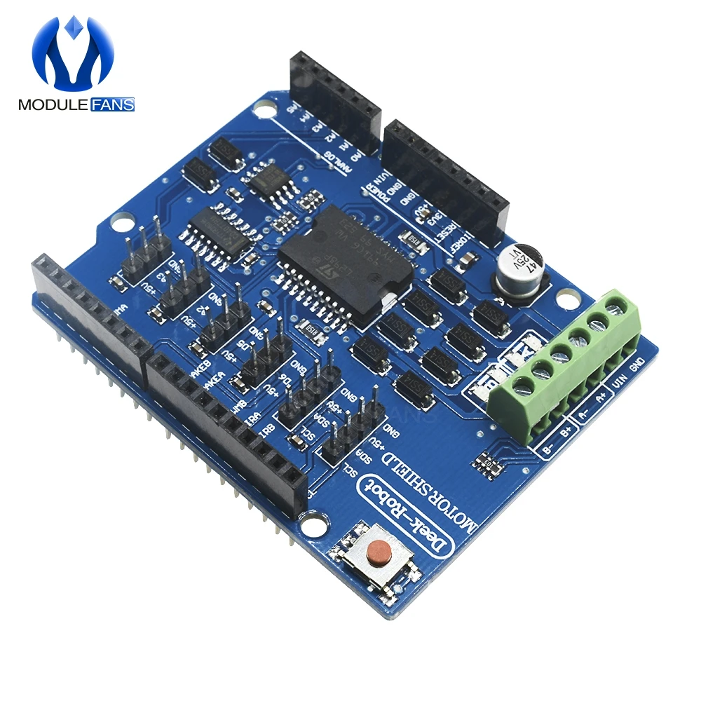
Der Schlüsselkomponente in diesem Projekt ist das PCA9685-Modul, das 16 Kanäle für PWM-Signale bereitstellt. Dieses Modul verwendet die I2C-Kommunikation, wobei die SDA- und SCL-Pins für die Datenübertragung zuständig sind. Jedes PCA9685 kann bis zu 16 Servos steuern, aber durch das Kaskadieren von zwei Modulen können wir 32 Servos gleichzeitig steuern.
Der Arduino dient als Controller und sendet Befehle an die PCA9685-Module. Jeder Servomotor wird an einen der Ausgangspins des PCA9685 angeschlossen, was eine präzise Steuerung ihrer Positionen ermöglicht. Eine ordnungsgemäße externe Stromversorgung ist entscheidend, da die Servos erheblichen Strom ziehen können.
Datenblattdetails
| Hersteller | Adafruit |
|---|---|
| Teilenummer | PCA9685 |
| Logik/IO-Spannung | 3,3 V bis 5,5 V |
| Versorgungsspannung | 5 V (extern für Servos) |
| Ausgangsstrom (pro Kanal) | ~20 mA |
| Spitzenstrom (pro Kanal) | ~25 mA |
| PWM-Frequenzrichtlinien | 40 Hz bis 1000 Hz |
| Eingabelogik-Schwellenwerte | 0,3 V (niedrig), 0,7 V (hoch) |
| Spannungsabfall / RDS(on)/ Sättigung | ~0,5 V |
| Thermische Grenzen | Betriebstemperatur: -40°C bis +85°C |
| Paket | 16-poliges TSSOP |
| Notizen / Varianten | Kann mehrere Boards für erweiterte Kontrolle verketten. |
- Sorgen Sie für eine angemessene Stromversorgung, um ein Stillstehen des Servos zu vermeiden.
- Verwenden Sie externe Stromversorgung für Servos; Arduino kann nicht ausreichend Strom liefern.
- Verbinden Sie den Ground des PCA9685 mit dem Ground des Arduino.
- Halten Sie den OE-Pin geerdet, um das Modul zu aktivieren.
- Beachten Sie die I2C-Adresse für jedes Modul; die Standardeinstellung ist 0x40 für das erste und 0x41 für das zweite.
Verdrahtungsanweisungen

Um die PCA9685-Module und Servos zu verkabeln, beginnen Sie damit, die Stromversorgung und die Masse zu verbinden. Verbinden Sie den VCC-Pin des PCA9685 mit dem 5V-Pin des Arduino und verbinden Sie den Masse-Pin mit dem GND des Arduino. Für die Servostromversorgung verwenden Sie ein externes Netzteil, das mit dem V+-Pin des PCA9685 verbunden ist.
Verbinden Sie als Nächstes die SDA- und SCL-Pins der PCA9685-Module mit den A4- bzw. A5-Pins des Arduino. Wenn Sie mehrere PCA9685-Module verwenden, verbinden Sie sie in einer Reihenfolge. Stellen Sie sicher, dass der OE-Pin mit dem Ground verbunden ist, um die Ausgänge zu aktivieren. Schließen Sie schließlich den Signaldraht jedes Servos an die entsprechenden PWM-Ausgangspins auf dem PCA9685 an (0-15 für das erste Modul und 16-31 für das zweite Modul).
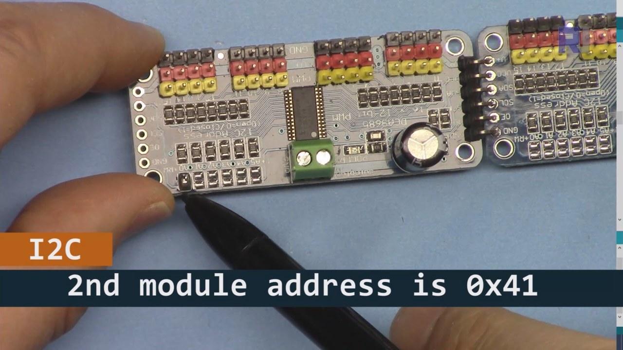
Wie im obigen Bild gezeigt, müssen Sie die auf der Platine 2 angegebenen Pins löten, die sich von der Platine 1 unterscheiden müssen. Auf diese Weise haben wir unterschiedliche I2C-Adressen und Sie können die Platine steuern.
Codebeispiele & Anleitung
Lass uns den Setup-Teil des Codes anschauen, der die PCA9685-Module initialisiert. Hier definieren wir die Adressen für jede Platine:
Adafruit_PWMServoDriver board1 = Adafruit_PWMServoDriver(0x40);
Adafruit_PWMServoDriver board2 = Adafruit_PWMServoDriver(0x41);
In diesem Auszug erstellen wir Instanzen des PCA9685-Treibers für beide Platinen und geben ihre I2C-Adressen an. Diese Einrichtung ist entscheidend, um sicherzustellen, dass unser Arduino mit beiden Modulen kommunizieren kann.
Diesetup()Die Funktion initialisiert die Boards und setzt die PWM-Frequenz:
void setup() {
  Serial.begin(9600);
  board1.begin();
  board2.begin();
  board1.setPWMFreq(60);  // Analog servos run at ~60 Hz updates
  board2.setPWMFreq(60);
}
Hier beginnen wir die serielle Kommunikation und stellen beide Boards so ein, dass sie mit einer Frequenz von 60 Hz arbeiten, was für die meisten Servos standardmäßig ist. Dies sorgt für einen reibungslosen Betrieb, während wir die Servos steuern.
Als Nächstes schauen wir uns die Steuerlogik imloop()Funktion:
for(int angle = 0; angle < 181; angle += 10) {
  for(int i = 0; i < 16; i++) {
    board1.setPWM(i, 0, angleToPulse(angle));
    board2.setPWM(i, 0, angleToPulse(angle));
  }
}
Diese Schleife erhöht den Winkel von 0 auf 180 Grad in Schritten von 10. Für jeden Winkel wird das PWM-Signal für alle Servos auf beiden Steuerungen gesetzt, sodass sie synchron von 0 auf 180 Grad und zurück bewegen können. DerangleToPulse()Die Funktion konvertiert den Winkel in die entsprechende Pulsbreite für die Servos.
Demonstration / Was zu erwarten ist
Sobald alles verkabelt ist und der Code hochgeladen wurde, sollten Sie sehen, wie alle 32 Servos zusammen bewegt werden und die Winkel sanft durchlaufen. Wenn Sie die Taste drücken, wird der Zustand aller Servos zwischen ein und aus umgeschaltet (im Video bei 00:00). Achten Sie auf umgekehrte Polarität und stellen Sie sicher, dass Ihre Servos für den gelieferten Strom ausgelegt sind, um Überhitzung zu vermeiden.
Video-Zeitstempel
- 00:00 Start
- 01:18 Einführung
- 04:30 Vorbereitung der Module
- 07:56 Verkabelung erklärt
- 10:25 Leistungsanforderung
- 11:33 Code erklärt
- 19:54 Code 2 erklärt (8 Servos zusammen auf jedem Board)
- 20:40 Demonstration 8 Servosteuerung zusammen
- 21:55 Demonstration Alle 32 Servos bewegen sich gemeinsam
- 22:28 Code für den Erklärungen des Druckknopfs
- 24:43 Verkabelung für Druckknopf erklärt
- 25:12 Demonstration der Verwendung eines Drucktaste-Schalters
Bilder


Dieses Tutorial ist Teil von: Ansteuerung von 16 oder 32 Servomotoren mit PCA9685
- Arduino-Code und Video für PCA9685 16-Kanal 12-Bit Servo-Controller V1
- Steuere 16 Servomotoren mit einem PCA9685-Modul und Arduino V2 Sketch #1: Eins nach dem anderen
- Steuerung von 16 Servomotoren mit einem PCA9685-Modul und Arduino V2-Sketch: Individuelle Servosteuerung
- Controlling 16 Servo Motors Using a PCA9685 Module and Arduino V2 Sketch #3: All Servos Together
- Steuerung eines 32 Servo-Motors mit einem PCA9685-Modul und einem ESP32 V4
- Steuere 32 Servos über Wi-Fi mit ESP32 und PCA9685 über Desktop oder Mobiltelefon V5
/*
 * Original source: https://github.com/adafruit/Adafruit-PWM-Servo-Driver-Library
 *
 * This is the Arduino code to use two PCA6985 boards and control 32 servo motor
 *
 * This is V3 Video on PCA9685: https://youtu.be/6P21wG7N6t4
 *  get this code and wiring from for this video:  http://robojax.com/RJT249
to learn better: watch the video for details (V1) and demo http://youtu.be/y8X9X10Tn1k


 * Written/updated by Ahmad Shamshiri for Robojax Video channel www.Robojax.com
 * Date: Dec 15, 2019, in Ajax, Ontario, Canada

 * Watch video for this code:
 *
 * Related Videos
V5 video of PCA9685 32 Servo with ESP32 with WiFi https://youtu.be/bvqfv-FrrLM
V4 video of PCA9685 32 Servo with ESP32 (no WiFi): https://youtu.be/JFdXB8Za5Os
V3 video of PCA9685 how to control 32 Servo motors https://youtu.be/6P21wG7N6t4
V2 Video of PCA9685 3 different ways to control Servo motors: https://youtu.be/bal2STaoQ1M
V1 Video introduction to PCA9685 to control 16 Servo  https://youtu.be/y8X9X10Tn1k
 * Disclaimer: this code is "AS IS" and for educational purpose only.


or make donation using PayPal http://robojax.com/L/?id=64

 *  * This code is "AS IS" without warranty or liability. Free to be used as long as you keep this note intact.*
 * This code has been download from Robojax.com
    This program is free software: you can redistribute it and/or modify
    it under the terms of the GNU General Public License as published by
    the Free Software Foundation, either version 3 of the License, or
    (at your option) any later version.

    This program is distributed in the hope that it will be useful,
    but WITHOUT ANY WARRANTY; without even the implied warranty of
    MERCHANTABILITY or FITNESS FOR A PARTICULAR PURPOSE.  See the
    GNU General Public License for more details.

    You should have received a copy of the GNU General Public License
    along with this program.  If not, see <https://www.gnu.org/licenses/>.
 */
#include <Wire.h>
#include <Adafruit_PWMServoDriver.h>

// called this way, it uses the default address 0x40
Adafruit_PWMServoDriver board1 = Adafruit_PWMServoDriver(0x40);
Adafruit_PWMServoDriver board2 = Adafruit_PWMServoDriver(0x41);

// Depending on your servo make, the pulse width min and max may vary, you
// want these to be as small/large as possible without hitting the hard stop
// for max range. You'll have to tweak them as necessary to match the servos you
// have!
// Watch video V1 to understand the two lines below: http://youtu.be/y8X9X10Tn1k
#define SERVOMIN  125 // this is the 'minimum' pulse length count (out of 4096)
#define SERVOMAX  575 // this is the 'maximum' pulse length count (out of 4096)


int servoNumber = 0;

void setup() {
  Serial.begin(9600);
  Serial.println("16 channel Servo test!");

  board1.begin();
  board2.begin();
  board1.setPWMFreq(60);  // Analog servos run at ~60 Hz updates
  board2.setPWMFreq(60);
  //yield();
}

// the code inside loop() has been updated by Robojax
void loop() {


    for( int angle =0; angle<181; angle +=10){
      for(int i=0; i<16; i++)
        {
            board2.setPWM(i, 0, angleToPulse(angle) );
            board1.setPWM(i, 0, angleToPulse(angle) );
        }
    }

// robojax PCA9865 16 channel Servo control
  delay(100);

}

/*
 * angleToPulse(int ang)
 * gets angle in degree and returns the pulse width
 * also prints the value on seial monitor
 * written by Ahmad Nejrabi for Robojax, Robojax.com
 */
int angleToPulse(int ang){
   int pulse = map(ang,0, 180, SERVOMIN,SERVOMAX);// map angle of 0 to 180 to Servo min and Servo max
   Serial.print("Angle: ");Serial.print(ang);
   Serial.print(" pulse: ");Serial.println(pulse);
   return pulse;
}/*
* Original source: https://github.com/adafruit/Adafruit-PWM-Servo-Driver-Library
*
* This is the Arduino code for two PAC6985 board to control 16 servo on each board
* total 32 servos using I2C communication
* get this code and wiring from for this video (V3): http://robojax.com/RJT249
watch the video for details (V2) and demo https://youtu.be/6P21wG7N6t4
* watch the video for details (V1) and demo http://youtu.be/y8X9X10Tn1k
* This code is #3 for V2 Video Watch the video :
* I have got 3 codes as follow:https://youtu.be/bal2STaoQ1M
*
#1-Arduino Code to run one by one all servos from 0 to 180°
#2-Arduino Code to control specific servos with specific angle
#3-Arduino Code to run 2 or all servos at together
* Written/updated by Ahmad Shamshiri for Robojax Video channel www.Robojax.com
* Date: Dec 16, 2017, in Ajax, Ontario, Canada
* Permission granted to share this code given that this
* note is kept with the code.
* Disclaimer: this code is "AS IS" and for educational purpose only.
* this code has been downloaded from http://robojax.com/
or make donation using PayPal http://robojax.com/L/?id=64
* * This code is "AS IS" without warranty or liability. Free to be used as long as you keep this note intact.*
* This code has been download from Robojax.com
This program is free software: you can redistribute it and/or modify
it under the terms of the GNU General Public License as published by
the Free Software Foundation, either version 3 of the License, or
(at your option) any later version.
This program is distributed in the hope that it will be useful,
but WITHOUT ANY WARRANTY; without even the implied warranty of
MERCHANTABILITY or FITNESS FOR A PARTICULAR PURPOSE. See the
GNU General Public License for more details.
You should have received a copy of the GNU General Public License
along with this program. If not, see <https://www.gnu.org/licenses/>.
*/
#include <Wire.h>
#include <Adafruit_PWMServoDriver.h>
// called this way, it uses the default address 0x40
Adafruit_PWMServoDriver board1 = Adafruit_PWMServoDriver(0x40);
Adafruit_PWMServoDriver board2 = Adafruit_PWMServoDriver(0x41);
// Depending on your servo make, the pulse width min and max may vary, you
// want these to be as small/large as possible without hitting the hard stop
// for max range. You'll have to tweak them as necessary to match the servos you
// have!
// Watch video V1 to understand the two lines below: http://youtu.be/y8X9X10Tn1k
#define SERVOMIN 125 // this is the 'minimum' pulse length count (out of 4096)
#define SERVOMAX 575 // this is the 'maximum' pulse length count (out of 4096)
int servoNumber = 0;
void setup() {
Serial.begin(9600);
Serial.println("16 channel Servo test!");
board1.begin();
board2.begin();
board1.setPWMFreq(60); // Analog servos run at ~60 Hz updates
board2.setPWMFreq(60);
//yield();
}
// the code inside loop() has been updated by Robojax
void loop() {
for( int angle =0; angle<181; angle +=10){
for(int i=0; i<8; i++)
{
board2.setPWM(i, 0, angleToPulse(angle) );
board1.setPWM(i, 0, angleToPulse(angle) );
}
}
for( int angle =0; angle<181; angle +=30){
for(int i=8; i<16; i++)
{
board2.setPWM(i, 0, angleToPulse(angle) );
board1.setPWM(i, 0, angleToPulse(angle) );
}
}
// robojax PCA9865 16 channel Servo control
delay(100);
}
/*
* angleToPulse(int ang)
* gets angle in degree and returns the pulse width
* also prints the value on serial monitor
* written by Ahmad Shamshiri for Robojax, Robojax.com
*/
int angleToPulse(int ang){
int pulse = map(ang,0, 180, SERVOMIN,SERVOMAX);// map angle of 0 to 180 to Servo min and Servo max
Serial.print("Angle: ");Serial.print(ang);
Serial.print(" pulse: ");Serial.println(pulse);
return pulse;
}
 /* Original source: https://github.com/adafruit/Adafruit-PWM-Servo-Driver-Library
 *
 * This is the Arduino code for two PAC6985 board  and push button

 * total 32 servos using I2C communication
 * get this code and wiring from for this video (V3):  http://robojax.com/RJT249


 * watch the video for details (V1) and demo http://youtu.be/y8X9X10Tn1k
 *  This code is #3 for V2 Video Watch the video :
 *  I have got 3 codes as follow:https://youtu.be/bal2STaoQ1M
 *
   #1-Arduino Code to run one by one all servos from 0 to 180°
   #2-Arduino Code to control specific servos with specific angle
   #3-Arduino Code to run 2 or all servos at together

 * Written/updated by Ahmad Shamshiri for Robojax Video channel www.Robojax.com
 * Date: Dec 16, 2017, in Ajax, Ontario, Canada
 * Permission granted to share this code given that this
 * note is kept with the code.
 * Disclaimer: this code is "AS IS" and for educational purpose only.


 *  * This code is "AS IS" without warranty or liability. Free to be used as long as you keep this note intact.*
 * This code has been download from Robojax.com
    This program is free software: you can redistribute it and/or modify
    it under the terms of the GNU General Public License as published by
    the Free Software Foundation, either version 3 of the License, or
    (at your option) any later version.

    This program is distributed in the hope that it will be useful,
    but WITHOUT ANY WARRANTY; without even the implied warranty of
    MERCHANTABILITY or FITNESS FOR A PARTICULAR PURPOSE.  See the
    GNU General Public License for more details.

    You should have received a copy of the GNU General Public License
    along with this program.  If not, see <https://www.gnu.org/licenses/>.
 */
#include <Wire.h>
#include <Adafruit_PWMServoDriver.h>

// called this way, it uses the default address 0x40
Adafruit_PWMServoDriver board1 = Adafruit_PWMServoDriver(0x40);
Adafruit_PWMServoDriver board2 = Adafruit_PWMServoDriver(0x41);

// Depending on your servo make, the pulse width min and max may vary, you
// want these to be as small/large as possible without hitting the hard stop
// for max range. You'll have to tweak them as necessary to match the servos you
// have!
// Watch video V1 to understand the two lines below: http://youtu.be/y8X9X10Tn1k
#define SERVOMIN  125 // this is the 'minimum' pulse length count (out of 4096)
#define SERVOMAX  575 // this is the 'maximum' pulse length count (out of 4096)

#define PUSH_BUTTON_PIN 2
#define OE_PIN 8

int boardState= LOW;
int showDebug=0;
int angle = 0;
int angleStep =10;

void setup() {
  Serial.begin(9600);
  Serial.println("16 channel Servo test!");

  board1.begin();
  board2.begin();
  board1.setPWMFreq(60);  // Analog servos run at ~60 Hz updates
  board2.setPWMFreq(60);

  pinMode(PUSH_BUTTON_PIN,INPUT_PULLUP);
  pinMode(OE_PIN, OUTPUT);
  digitalWrite(OE_PIN,LOW);//turn module ON

}

// the code inside loop() has been updated by Robojax
void loop() {
   if(digitalRead(PUSH_BUTTON_PIN) == LOW)
   {
    boardState = 1-boardState;
    Serial.println("push button pressed");
    delay(200); // give the finger time
   }
 digitalWrite(OE_PIN, boardState);
    for( int angle =0; angle<181; angle +=angleStep){
      delay(50);
      for(int i=0; i<16; i++)
        {
          board1.setPWM(i, 0, angleToPulse(angle) );
          board2.setPWM(i, 0, angleToPulse(angle) );
        }
    }

// robojax PCA9865 16 channel Servo control
  delay(100);

}

/*
 * angleToPulse(int ang)
 * gets angle in degree and returns the pulse width
 * also prints the value on serial monitor
 * written by Ahmad Shamshiri for Robojax, Robojax.com
 */
int angleToPulse(int ang){
   int pulse = map(ang,0, 180, SERVOMIN,SERVOMAX);// map angle of 0 to 180 to Servo min and Servo max
  if(showDebug)
  {
   Serial.print("Angle: ");Serial.print(ang);
   Serial.print(" pulse: ");Serial.println(pulse);
  }
   return pulse;
}

/*
 * updateState()
 * @brief reads push buttons and updates values
 * @param none
 * @return no return
 * Written by Ahmad Shamshiri for robojax.com
 * on Nov 01, 2019 at 18:10 in Ajax, Ontario, Canada
 */
void updateState()
{
   if(digitalRead(PUSH_BUTTON_PIN) == LOW)
   {
    boardState = 1-boardState;
    Serial.println("push button pressed");
    delay(200); // give the finger time
   }
   digitalWrite(OE_PIN, boardState);
}//updateState end
Dinge, die Sie vielleicht brauchen
-
AmazonKaufe PCA9685 bei Amazonamzn.to
-
eBayPCA9685 bei eBay kaufenebay.us
-
AliExpressPCA9685 bei AliExpress kaufens.click.aliexpress.com
-
BanggoodKaufen Sie PCA9685 bei Bangoodbanggood.com
Ressourcen & Referenzen
Noch keine Ressourcen vorhanden.
Dateien📁
Arduino-Bibliotheken (zip)
-
Adafruit-PWM-Servo-Treiber-Bibliothek-master
Adafruit-PWM-Servo-Driver-Library-master.zip0.02 MB