هذا الدليل جزء من: التحكم في محرك سيرفو 16 أو 32 باستخدام PCA9685
تساعدك هذه المجموعة من الدروس التعليمية المصحوبة بمقاطع فيديو على التحكم في 32 محرك سيرفو أو أكثر باستخدام أردوينو أونو، أو نانو، أو ميني، أو إي إس بي 32. جميع الأكواد متوفرة.

التحكم في محرك سيرفو 32 باستخدام وحدة PCA9685 وبرنامج Arduino V3 الرسم التخطيطي #1: جميع السيرفوهات معًا
في هذا الدرس، سنتعلم كيفية التحكم في 32 محرك سيرفو باستخدام وحدتي قيادة PWM من نوع PCA9685 متصلتين بآردوينو. تعتبر PCA9685 وحدة متعددة الاستخدامات تتيح التحكم بسهولة في العديد من المحركات عبر الاتصال I2C. بحلول نهاية هذا المشروع، ستكون قادرًا على تحريك جميع 32 محرك سيرفو في تناغم مع إعداد بسيط.

سنقوم أيضًا بتنفيذ زر ضغط يمكنه تشغيل أو إيقاف تشغيل جميع السيرفو في نفس الوقت. تضيف هذه الميزة طبقة إضافية من التحكم وتجعل المشروع أكثر تفاعلًا. لفهم بصري للإعداد والرمز، تأكد من تفقد الفيديو المصاحب (في الفيديو عند :00).
شرح الأجهزة
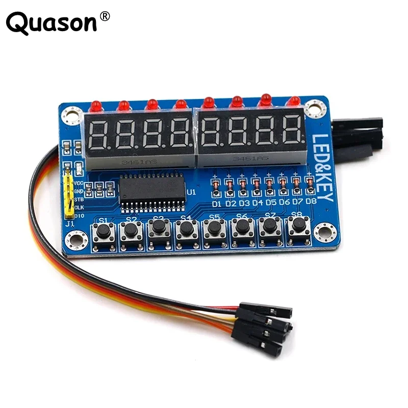
المكون الرئيسي في هذا المشروع هو وحدة PCA9685، التي توفر 16 قناة لإشارات PWM. تستخدم هذه الوحدة اتصال I2C، حيث تتعامل دبوسا SDA و SCL مع نقل البيانات. يمكن لكل PCA9685 التحكم في ما يصل إلى 16 سيرفو، ولكن من خلال توصيل وحدتين معًا، يمكننا التحكم في 32 سيرفو في الوقت نفسه.
تعمل لوحة الأردوينو كجهاز تحكم، ترسل الأوامر إلى وحدات PCA9685. سيتم توصيل كل محرك سيرفو بأحد دبابيس الإخراج على PCA9685، مما يسمح بالتحكم الدقيق في مواضعها. من الضروري توفير مصدر طاقة خارجي مناسب، حيث يمكن أن تسحب المحركات تياراً كبيراً.
تفاصيل ورقة البيانات
| الصانع | أدا فرويت |
|---|---|
| رقم الجزء | PCA9685 |
| جهد الدوائر المنطقية/المدخلات والمخرجات | ۳.۳ فولت إلى ۵.۵ فولت |
| جهد الإمداد | ٥ فولت (خارجي للخدمات) |
| التيار الناتج (لكل قناة) | حوالي 20 مللي أمبير |
| التيار الذروي (لكل قناة) | حوالي 25 مللي أمبير |
| توجيه تردد PWM | 40 هرتز إلى 1000 هرتز |
| عتبات منطق الإدخال | 0.3 فولت (منخفض)، 0.7 فولت (مرتفع) |
| انخفاض الجهد / رDS(تشغيل)/ تشبع | ~0.5 ف |
| الحدود الحرارية | درجة حرارة التشغيل: -40°م إلى +85°م |
| حزمة | 16 دبوس TSSOP |
| ملاحظات / متغيرات | يمكن ربط عدة لوحات لزيادة التحكم |
- تأكد من توفير مصدر طاقة مناسب لتجنب توقف السيرفو.
- استخدم طاقة خارجية للسيرفو؛ الأردوينو لا يمكنه توفير تيار كاف.
- قم بتوصيل الأرضي الخاص بـ PCA9685 بالأرضي الخاص بأردوينو.
- ابقِ دبوس OE مؤرضًا لتمكين الوحدة.
- لاحظ عنوان I2C لكل وحدة؛ الافتراضي هو 0x40 للأولى و 0x41 للثانية.
تعليمات التوصيل

لتوصيل وحدات PCA9685 والسيرفو، ابدأ بتوصيل الطاقة والأرضي. قم بتوصيل دبوس VCC على PCA9685 بدبوس 5V على الأردوينو، وقم بتوصيل دبوس الأرضي إلى GND الخاص بالأردوينو. لتغذية السيرفو، استخدم مصدر طاقة خارجي متصل بدبوس V+ على PCA9685.
بعد ذلك، قم بتوصيل دبابيس SDA و SCL لوحدات PCA9685 بدبابيس A4 و A5 الخاصة بآردوينو على التوالي. إذا كنت تستخدم وحدات PCA9685 متعددة، قم بتوصيلها في سلسلة سلسلة. تأكد من توصيل دبوس OE بالأرض لتمكين المخرجات. أخيرًا، قم بتوصيل سلك إشارة كل سيرفو بدبابيس إخراج PWM المناسبة على PCA9685 (0-15 للوحدة الأولى و 16-31 للوحدة الثانية).
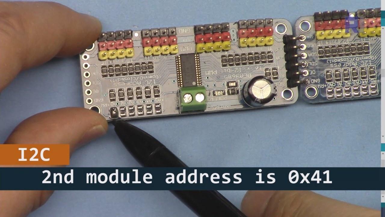
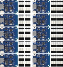
كما هو موضح في الصورة أعلاه، يجب عليك لحام المسامير المعروضة على اللوحة 2 ويجب أن تكون مختلفة عن اللوحة 1. بهذه الطريقة سيكون لدينا عنوان i2C مختلف ويمكنك التحكم في اللوحة.
أمثلة الشيفرة & شرح تفصيلي
لنلق نظرة على قسم الإعداد من الكود الذي يقوم بتهيئة وحدات PCA9685. هنا نحدد العناوين لكل لوحة:
Adafruit_PWMServoDriver board1 = Adafruit_PWMServoDriver(0x40);
Adafruit_PWMServoDriver board2 = Adafruit_PWMServoDriver(0x41);
في هذا المقتطف، نقوم بإنشاء حالات من برنامج تشغيل PCA9685 لكل من اللوحتين، مع تحديد عناوين I2C الخاصة بهما. هذه الإعدادات مهمة لضمان أن يمكن لآردوينو الخاص بنا التواصل مع كلا الوحدتين.
الـsetup()تقوم الدالة بتهيئة اللوحات وتحديد تردد PWM:
void setup() {
  Serial.begin(9600);
  board1.begin();
  board2.begin();
  board1.setPWMFreq(60);  // Analog servos run at ~60 Hz updates
  board2.setPWMFreq(60);
}
هنا، نبدأ الاتصال التسلسلي ونضبط كلا اللوحين للعمل على تردد 60 هرتز، وهو معيار لمعظم السيرفو. هذا يضمن تشغيلًا سلسًا بينما نتحكم في السيرفوهات.
بعد ذلك، دعنا نلقي نظرة على منطق التحكم في الـloop()وظيفة:
for(int angle = 0; angle < 181; angle += 10) {
  for(int i = 0; i < 16; i++) {
    board1.setPWM(i, 0, angleToPulse(angle));
    board2.setPWM(i, 0, angleToPulse(angle));
  }
}
تزيد هذه الحلقة الزاوية من 0 إلى 180 درجة بخطوات قدرها 10. لكل زاوية، يتم تعيين إشارة PWM لجميع السيرفووات على كلا اللوحين، مما يسمح لهم بالتحرك بتزامن من 0 إلى 180 درجة والعودة.angleToPulse()تقوم الدالة بتحويل الزاوية إلى عرض نبضة correspondente للخوادم.
عرض / ماذا تتوقع
بمجرد توصيل كل شيء وتحميل الكود، يجب أن ترى جميع المحركات الـ 32 تعمل معًا، تتحرك بسلاسة بين الزوايا. إذا ضغطت على زر الدفع، فسوف يغير حالة جميع المحركات بين التشغيل والإيقاف (في الفيديو عند 00:00). كن حذرًا من القطبية المعكوسة وتأكد من أن المحركات الخاصة بك مصنفة لتيار الطاقة المزوّدة لتجنب ارتفاع درجة الحرارة.
توقيتات الفيديو
- :00 بدء
- :18 مقدمة
- 04:30 إعداد الوحدات
- 07:56 شرح الأسلاك
- 10:25 متطلبات الطاقة
- 11:33 شرح الكود
- 19:54 الشيفرة 2 مفسرة (8 سيرفو معًا على كل لوحة)
- ٢٠:٤٠ عرض التحكم مع ٨ سيرفو معًا
- 21:55 عرض جميع 32 سيرفو تتحرك معًا
- :28 تم شرح رمز زر الضغط
- 24:43 شرح توصيل زر الدفع
- :12 عرض لاستخدام مفتاح الدفع
الصور


هذا الدليل هو جزء من: التحكم في محرك سيرفو 16 أو 32 باستخدام PCA9685
- كود أردوينو وفيديو لمتحكم السيرفو PCA9685 ذو 16 قناة و12 بت V1
- Control 16 Servo Motors Using a PCA9685 Module and Arduino V2 Sketch #1: One-by-One
- التحكم في 16 محرك سيرفو باستخدام وحدة PCA9685 وكود أردوينو V2: التحكم الفردي في السيرفو
- Controlling 16 Servo Motors Using a PCA9685 Module and Arduino V2 Sketch #3: All Servos Together
- التحكم في محرك سيرفو 32 باستخدام وحدة PCA9685 و ESP32 V4
- التحكم في 32 سيرفو عبر الواي فاي باستخدام ESP32 و PCA9685 من خلال الكمبيوتر المكتبي أو الهاتف المحمول V5
/*
 * Original source: https://github.com/adafruit/Adafruit-PWM-Servo-Driver-Library
 *
 * This is the Arduino code to use two PCA6985 boards and control 32 servo motor
 *
 * This is V3 Video on PCA9685: https://youtu.be/6P21wG7N6t4
 *  get this code and wiring from for this video:  http://robojax.com/RJT249
to learn better: watch the video for details (V1) and demo http://youtu.be/y8X9X10Tn1k


 * Written/updated by Ahmad Shamshiri for Robojax Video channel www.Robojax.com
 * Date: Dec 15, 2019, in Ajax, Ontario, Canada

 * Watch video for this code:
 *
 * Related Videos
V5 video of PCA9685 32 Servo with ESP32 with WiFi https://youtu.be/bvqfv-FrrLM
V4 video of PCA9685 32 Servo with ESP32 (no WiFi): https://youtu.be/JFdXB8Za5Os
V3 video of PCA9685 how to control 32 Servo motors https://youtu.be/6P21wG7N6t4
V2 Video of PCA9685 3 different ways to control Servo motors: https://youtu.be/bal2STaoQ1M
V1 Video introduction to PCA9685 to control 16 Servo  https://youtu.be/y8X9X10Tn1k
 * Disclaimer: this code is "AS IS" and for educational purpose only.


or make donation using PayPal http://robojax.com/L/?id=64

 *  * This code is "AS IS" without warranty or liability. Free to be used as long as you keep this note intact.*
 * This code has been download from Robojax.com
    This program is free software: you can redistribute it and/or modify
    it under the terms of the GNU General Public License as published by
    the Free Software Foundation, either version 3 of the License, or
    (at your option) any later version.

    This program is distributed in the hope that it will be useful,
    but WITHOUT ANY WARRANTY; without even the implied warranty of
    MERCHANTABILITY or FITNESS FOR A PARTICULAR PURPOSE.  See the
    GNU General Public License for more details.

    You should have received a copy of the GNU General Public License
    along with this program.  If not, see <https://www.gnu.org/licenses/>.
 */
#include <Wire.h>
#include <Adafruit_PWMServoDriver.h>

// called this way, it uses the default address 0x40
Adafruit_PWMServoDriver board1 = Adafruit_PWMServoDriver(0x40);
Adafruit_PWMServoDriver board2 = Adafruit_PWMServoDriver(0x41);

// Depending on your servo make, the pulse width min and max may vary, you
// want these to be as small/large as possible without hitting the hard stop
// for max range. You'll have to tweak them as necessary to match the servos you
// have!
// Watch video V1 to understand the two lines below: http://youtu.be/y8X9X10Tn1k
#define SERVOMIN  125 // this is the 'minimum' pulse length count (out of 4096)
#define SERVOMAX  575 // this is the 'maximum' pulse length count (out of 4096)


int servoNumber = 0;

void setup() {
  Serial.begin(9600);
  Serial.println("16 channel Servo test!");

  board1.begin();
  board2.begin();
  board1.setPWMFreq(60);  // Analog servos run at ~60 Hz updates
  board2.setPWMFreq(60);
  //yield();
}

// the code inside loop() has been updated by Robojax
void loop() {


    for( int angle =0; angle<181; angle +=10){
      for(int i=0; i<16; i++)
        {
            board2.setPWM(i, 0, angleToPulse(angle) );
            board1.setPWM(i, 0, angleToPulse(angle) );
        }
    }

// robojax PCA9865 16 channel Servo control
  delay(100);

}

/*
 * angleToPulse(int ang)
 * gets angle in degree and returns the pulse width
 * also prints the value on seial monitor
 * written by Ahmad Nejrabi for Robojax, Robojax.com
 */
int angleToPulse(int ang){
   int pulse = map(ang,0, 180, SERVOMIN,SERVOMAX);// map angle of 0 to 180 to Servo min and Servo max
   Serial.print("Angle: ");Serial.print(ang);
   Serial.print(" pulse: ");Serial.println(pulse);
   return pulse;
}/*
* Original source: https://github.com/adafruit/Adafruit-PWM-Servo-Driver-Library
*
* This is the Arduino code for two PAC6985 board to control 16 servo on each board
* total 32 servos using I2C communication
* get this code and wiring from for this video (V3): http://robojax.com/RJT249
watch the video for details (V2) and demo https://youtu.be/6P21wG7N6t4
* watch the video for details (V1) and demo http://youtu.be/y8X9X10Tn1k
* This code is #3 for V2 Video Watch the video :
* I have got 3 codes as follow:https://youtu.be/bal2STaoQ1M
*
#1-Arduino Code to run one by one all servos from 0 to 180°
#2-Arduino Code to control specific servos with specific angle
#3-Arduino Code to run 2 or all servos at together
* Written/updated by Ahmad Shamshiri for Robojax Video channel www.Robojax.com
* Date: Dec 16, 2017, in Ajax, Ontario, Canada
* Permission granted to share this code given that this
* note is kept with the code.
* Disclaimer: this code is "AS IS" and for educational purpose only.
* this code has been downloaded from http://robojax.com/
or make donation using PayPal http://robojax.com/L/?id=64
* * This code is "AS IS" without warranty or liability. Free to be used as long as you keep this note intact.*
* This code has been download from Robojax.com
This program is free software: you can redistribute it and/or modify
it under the terms of the GNU General Public License as published by
the Free Software Foundation, either version 3 of the License, or
(at your option) any later version.
This program is distributed in the hope that it will be useful,
but WITHOUT ANY WARRANTY; without even the implied warranty of
MERCHANTABILITY or FITNESS FOR A PARTICULAR PURPOSE. See the
GNU General Public License for more details.
You should have received a copy of the GNU General Public License
along with this program. If not, see <https://www.gnu.org/licenses/>.
*/
#include <Wire.h>
#include <Adafruit_PWMServoDriver.h>
// called this way, it uses the default address 0x40
Adafruit_PWMServoDriver board1 = Adafruit_PWMServoDriver(0x40);
Adafruit_PWMServoDriver board2 = Adafruit_PWMServoDriver(0x41);
// Depending on your servo make, the pulse width min and max may vary, you
// want these to be as small/large as possible without hitting the hard stop
// for max range. You'll have to tweak them as necessary to match the servos you
// have!
// Watch video V1 to understand the two lines below: http://youtu.be/y8X9X10Tn1k
#define SERVOMIN 125 // this is the 'minimum' pulse length count (out of 4096)
#define SERVOMAX 575 // this is the 'maximum' pulse length count (out of 4096)
int servoNumber = 0;
void setup() {
Serial.begin(9600);
Serial.println("16 channel Servo test!");
board1.begin();
board2.begin();
board1.setPWMFreq(60); // Analog servos run at ~60 Hz updates
board2.setPWMFreq(60);
//yield();
}
// the code inside loop() has been updated by Robojax
void loop() {
for( int angle =0; angle<181; angle +=10){
for(int i=0; i<8; i++)
{
board2.setPWM(i, 0, angleToPulse(angle) );
board1.setPWM(i, 0, angleToPulse(angle) );
}
}
for( int angle =0; angle<181; angle +=30){
for(int i=8; i<16; i++)
{
board2.setPWM(i, 0, angleToPulse(angle) );
board1.setPWM(i, 0, angleToPulse(angle) );
}
}
// robojax PCA9865 16 channel Servo control
delay(100);
}
/*
* angleToPulse(int ang)
* gets angle in degree and returns the pulse width
* also prints the value on serial monitor
* written by Ahmad Shamshiri for Robojax, Robojax.com
*/
int angleToPulse(int ang){
int pulse = map(ang,0, 180, SERVOMIN,SERVOMAX);// map angle of 0 to 180 to Servo min and Servo max
Serial.print("Angle: ");Serial.print(ang);
Serial.print(" pulse: ");Serial.println(pulse);
return pulse;
}
 /* Original source: https://github.com/adafruit/Adafruit-PWM-Servo-Driver-Library
 *
 * This is the Arduino code for two PAC6985 board  and push button

 * total 32 servos using I2C communication
 * get this code and wiring from for this video (V3):  http://robojax.com/RJT249


 * watch the video for details (V1) and demo http://youtu.be/y8X9X10Tn1k
 *  This code is #3 for V2 Video Watch the video :
 *  I have got 3 codes as follow:https://youtu.be/bal2STaoQ1M
 *
   #1-Arduino Code to run one by one all servos from 0 to 180°
   #2-Arduino Code to control specific servos with specific angle
   #3-Arduino Code to run 2 or all servos at together

 * Written/updated by Ahmad Shamshiri for Robojax Video channel www.Robojax.com
 * Date: Dec 16, 2017, in Ajax, Ontario, Canada
 * Permission granted to share this code given that this
 * note is kept with the code.
 * Disclaimer: this code is "AS IS" and for educational purpose only.


 *  * This code is "AS IS" without warranty or liability. Free to be used as long as you keep this note intact.*
 * This code has been download from Robojax.com
    This program is free software: you can redistribute it and/or modify
    it under the terms of the GNU General Public License as published by
    the Free Software Foundation, either version 3 of the License, or
    (at your option) any later version.

    This program is distributed in the hope that it will be useful,
    but WITHOUT ANY WARRANTY; without even the implied warranty of
    MERCHANTABILITY or FITNESS FOR A PARTICULAR PURPOSE.  See the
    GNU General Public License for more details.

    You should have received a copy of the GNU General Public License
    along with this program.  If not, see <https://www.gnu.org/licenses/>.
 */
#include <Wire.h>
#include <Adafruit_PWMServoDriver.h>

// called this way, it uses the default address 0x40
Adafruit_PWMServoDriver board1 = Adafruit_PWMServoDriver(0x40);
Adafruit_PWMServoDriver board2 = Adafruit_PWMServoDriver(0x41);

// Depending on your servo make, the pulse width min and max may vary, you
// want these to be as small/large as possible without hitting the hard stop
// for max range. You'll have to tweak them as necessary to match the servos you
// have!
// Watch video V1 to understand the two lines below: http://youtu.be/y8X9X10Tn1k
#define SERVOMIN  125 // this is the 'minimum' pulse length count (out of 4096)
#define SERVOMAX  575 // this is the 'maximum' pulse length count (out of 4096)

#define PUSH_BUTTON_PIN 2
#define OE_PIN 8

int boardState= LOW;
int showDebug=0;
int angle = 0;
int angleStep =10;

void setup() {
  Serial.begin(9600);
  Serial.println("16 channel Servo test!");

  board1.begin();
  board2.begin();
  board1.setPWMFreq(60);  // Analog servos run at ~60 Hz updates
  board2.setPWMFreq(60);

  pinMode(PUSH_BUTTON_PIN,INPUT_PULLUP);
  pinMode(OE_PIN, OUTPUT);
  digitalWrite(OE_PIN,LOW);//turn module ON

}

// the code inside loop() has been updated by Robojax
void loop() {
   if(digitalRead(PUSH_BUTTON_PIN) == LOW)
   {
    boardState = 1-boardState;
    Serial.println("push button pressed");
    delay(200); // give the finger time
   }
 digitalWrite(OE_PIN, boardState);
    for( int angle =0; angle<181; angle +=angleStep){
      delay(50);
      for(int i=0; i<16; i++)
        {
          board1.setPWM(i, 0, angleToPulse(angle) );
          board2.setPWM(i, 0, angleToPulse(angle) );
        }
    }

// robojax PCA9865 16 channel Servo control
  delay(100);

}

/*
 * angleToPulse(int ang)
 * gets angle in degree and returns the pulse width
 * also prints the value on serial monitor
 * written by Ahmad Shamshiri for Robojax, Robojax.com
 */
int angleToPulse(int ang){
   int pulse = map(ang,0, 180, SERVOMIN,SERVOMAX);// map angle of 0 to 180 to Servo min and Servo max
  if(showDebug)
  {
   Serial.print("Angle: ");Serial.print(ang);
   Serial.print(" pulse: ");Serial.println(pulse);
  }
   return pulse;
}

/*
 * updateState()
 * @brief reads push buttons and updates values
 * @param none
 * @return no return
 * Written by Ahmad Shamshiri for robojax.com
 * on Nov 01, 2019 at 18:10 in Ajax, Ontario, Canada
 */
void updateState()
{
   if(digitalRead(PUSH_BUTTON_PIN) == LOW)
   {
    boardState = 1-boardState;
    Serial.println("push button pressed");
    delay(200); // give the finger time
   }
   digitalWrite(OE_PIN, boardState);
}//updateState end
الأشياء التي قد تحتاجها
-
أمازونشراء PCA9685 من أمازونamzn.to
-
إي باياشترِ PCA9685 من eBayebay.us
-
علي إكسبريساشترِ PCA9685 من علي إكسبريسs.click.aliexpress.com
-
بانجوداشترِ PCA9685 من بانجودbanggood.com
الموارد والمراجع
لا توجد موارد حتى الآن.
ملفات📁
مكتبات أردوينو (ملف مضغوط)
-
آدا فروت - مكتبة سائق السيرفو PWM - ماستر
Adafruit-PWM-Servo-Driver-Library-master.zip0.02 MB