Este tutorial es parte de: Control de 16 o 32 servomotores con PCA9685
Esta colección de tutoriales con video te ayuda a controlar 32 o más servomotores con Arduino UNO, Nano, Mini o ESP32. Se proporcionan todos los códigos.

Controla 16 servomotores utilizando un módulo PCA9685 y un sketch de Arduino V2 #1: Uno por uno.
En este tutorial, aprenderemos a controlar hasta 16 servomotores utilizando un módulo PCA9685 y un Arduino. El PCA9685 es un controlador PWM de 16 canales y 12 bits que permite un control preciso de los servomotores. Al seguir esta guía, podrás controlar individualmente cada servomotor y ajustarlos a ángulos específicos, logrando una variedad de movimientos robóticos.
Comenzaremos discutiendo los componentes de hardware que necesitarás para este proyecto, seguidos de instrucciones de cableado detalladas. Después de eso, repasaremos el código paso a paso, destacando identificadores clave y sus roles en el control de los servomotores. Para una comprensión más clara, puede que desees consultar el video acompañado (en el video a las 00:00).
Hardware Explicado
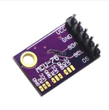
El componente principal de este proyecto es el módulo PCA9685, que es responsable de generar señales PWM para controlar los servos. Cada servo está conectado a uno de los 16 canales en el PCA9685, lo que permite un control independiente. El módulo se comunica con el Arduino utilizando el protocolo I2C, requiriendo solo dos cables: SDA y SCL.
Además del PCA9685, necesitarás una placa Arduino, 16 servomotores y una fuente de alimentación externa. La fuente de alimentación externa es crucial porque el Arduino por sí solo puede no proporcionar suficiente corriente para alimentar todos los servos simultáneamente. Cada servo generalmente opera a 5V, así que asegúrate de que tu fuente de alimentación cumpla con este requisito.
Detalles de la ficha técnica
| Fabricante | NXP Semiconductores |
|---|---|
| Número de parte | PCA9685 |
| Voltaje de lógica/IO | 2.3 - 5.5 V |
| Voltaje de suministro | 5 V |
| Corriente de salida (por canal) | 25 mA |
| Orientación sobre la frecuencia PWM | 60 Hz |
| Umbrales de lógica de entrada | 0.3VCC (bajo) / 0.7VCC (alto) |
| Caída de tensión / RDS(on)/ saturación | - |
| Límites térmicos | - |
| Paquete | TSSOP-28 / VQFN-28 |
| Notas / variantes | - |
- Conecte una fuente de alimentación externa de 5V para los servos.
- Utiliza I2C para la comunicación, conectando SDA a A4 y SCL a A5 en el Arduino.
- Asegúrate de que todos los grounds sean comunes entre el Arduino y el PCA9685.
- Ajuste los anchos de pulso de acuerdo con los servos específicos utilizados.
- Mantenga un enfriamiento adecuado para el PCA9685 si alimenta muchos servos simultáneamente.
Instrucciones de cableado
Para conectar el módulo PCA9685 al Arduino y los motores servo, comienza conectando la fuente de alimentación externa de 5V al terminal V+ del PCA9685. Conecta el suelo de la fuente de alimentación al terminal de tierra del PCA9685, así como a la tierra del Arduino.
A continuación, conecta los pines SDA y SCL del PCA9685 a los pines correspondientes en el Arduino (SDA a A4 y SCL a A5). Cada servo motor tendrá tres cables: tierra (generalmente negro o marrón), VCC (típicamente rojo) y señal (a menudo amarillo o blanco). Conecta el cable de tierra de cada servo al terminal de tierra del PCA9685, el cable VCC al terminal V+ y el cable de señal a los canales respectivos (0-15) en el PCA9685. Asegúrate de conectar el cable de señal en el orden correcto para cada servo.
Ejemplos de código y guía paso a paso
Ahora procederemos a revisar el código que controla los servomotores uno por uno. El código comienza importando las bibliotecas necesarias para la comunicación I2C y el módulo PCA9685. El siguiente fragmento inicializa el objeto PCA9685:
#include
#include

Adafruit_PWMServoDriver pwm = Adafruit_PWMServoDriver(); // Initialize PCA9685
En la función de configuración, inicializamos el monitor serial y establecemos la frecuencia PWM para los servos:
void setup() {
  Serial.begin(9600); // Start serial communication
  pwm.begin(); // Initialize PCA9685
  pwm.setPWMFreq(60); // Set frequency to 60 Hz for servos
}
El bucle principal contiene dos bucles anidados: el bucle exterior itera a través de cada uno de los 16 servos, mientras que el bucle interior cambia gradualmente el ángulo de 0 a 180 grados.
void loop() {
  for(int i=0; i<16; i++) {
    for(int angle = 0; angle<181; angle += 10) {
      delay(50); // Wait for servo to move
      pwm.setPWM(i, 0, angleToPulse(angle)); // Set servo position
    }
  }
  delay(1000); // Wait before repeating
}
Esta estructura permite que cada servo se mueva a su ángulo designado en incrementos de 10 grados, ofreciendo transiciones suaves. La funciónangleToPulse(int ang)convierte los valores de ángulo en anchos de pulso apropiados para los servos:
int angleToPulse(int ang) {
   int pulse = map(ang, 0, 180, SERVOMIN, SERVOMAX); // Map angle to pulse width
   return pulse; // Return pulse width
}
Esta función es esencial para traducir el ángulo deseado en una señal PWM que el PCA9685 puede entender y transmitir a los servomotores. Para más detalles, recuerda que el código completo se carga al final del artículo.
Demostración / Qué Esperar
Una vez que todo esté conectado correctamente y el código esté cargado, deberías ver cada servo moverse a sus respectivos ángulos uno tras otro. Si encuentras algún problema, revisa tus conexiones y asegúrate de tener una fuente de alimentación estable para los servos. Si los servos no están respondiendo como se esperaba, verifica las señales PWM que se envían a través del PCA9685.
Timestamps de video
- 00:00 Detalles del módulo con el chip PCA9685
- 06:14 Agregando la biblioteca necesaria para el PCA9685
- 07:14 Cargando el código de ejemplo
- 07:35 Código explicado
- 11:31 Código simplificado de Arduino para PCA9685
- 12:00 Encontrar el valor mínimo y máximo para su servo
- 18:27 Mapeo del ángulo de pulso a ancho de pulso
- 20:05 Creando un método separado para el mapeo
- 20:55 Usando un bucle for para probar todos los ángulos para el mapeo
Este tutorial es parte de: Control de 16 o 32 servomotores con PCA9685
- Código y vídeo de Arduino para el controlador de servos PCA9685 de 16 canales y 12 bits V1
- Controlando 16 Servomotores utilizando un módulo PCA9685 y el sketch de Arduino V2: Control individual de servos.
- Controlling 16 Servo Motors Using a PCA9685 Module and Arduino V2 Sketch #3: All Servos Together
- Controlando un motor servo de 32 utilizando un módulo PCA9685 y el sketch de Arduino V3 #1: Todos los servos juntos
- Controlando un motor servo de 32 utilizando un módulo PCA9685 y un ESP32 V4
- Controla 32 servos por Wi-Fi utilizando ESP32 y PCA9685 a través de escritorio o teléfono móvil V5
/*
 * Original source: https://github.com/adafruit/Adafruit-PWM-Servo-Driver-Library
 * PCA9685 Video V2, Arduino Code-1
 * This is the Arduino code PAC6985 16 channel servo controller
 * watch the video for details (V1) and demo http://youtu.be/y8X9X10Tn1k
 *  This code is #1 for V2 Video Watch the video :https://youtu.be/bal2STaoQ1M
get this code and wiring from https://robojax.com/RTJ243
 *  I have got 3 codes as follow:
   #1-Arduino Code to run one by one all servos from 0 to 180°
   #2-Arduino Code to control specific servos with specific angle
   #3-Arduino Code to run 2 or all servos at together

 * Written/updated by Ahmad Shamshiri for Robojax Video channel www.Robojax.com
 * Date: Dec 16, 2017, in Ajax, Ontario, Canada

 * Watch video for this code:
 *
 * Related Videos
V5 video of PCA9685 32 Servo with ESP32 with WiFi https://youtu.be/bvqfv-FrrLM
V4 video of PCA9685 32 Servo with ESP32 (no WiFi): https://youtu.be/JFdXB8Za5Os
V3 video of PCA9685 how to control 32 Servo motors https://youtu.be/6P21wG7N6t4
V2 Video of PCA9685 3 different ways to control Servo motors: https://youtu.be/bal2STaoQ1M
V1 Video introduction to PCA9685 to control 16 Servo  https://youtu.be/y8X9X10Tn1k

 * Disclaimer: this code is "AS IS" and for educational purpose only.
 * this code has been downloaded from https://robojax.com


or make donation using PayPal http://robojax.com/L/?id=64

 *  * This code is "AS IS" without warranty or liability. Free to be used as long as you keep this note intact.*
 * This code has been download from Robojax.com
    This program is free software: you can redistribute it and/or modify
    it under the terms of the GNU General Public License as published by
    the Free Software Foundation, either version 3 of the License, or
    (at your option) any later version.

    This program is distributed in the hope that it will be useful,
    but WITHOUT ANY WARRANTY; without even the implied warranty of
    MERCHANTABILITY or FITNESS FOR A PARTICULAR PURPOSE.  See the
    GNU General Public License for more details.

    You should have received a copy of the GNU General Public License
    along with this program.  If not, see <https://www.gnu.org/licenses/>.
 */

/***************************************************
  This is an example for our Adafruit 16-channel PWM & Servo driver
  Servo test - this will drive 16 servos, one after the other

  Pick one up today in the adafruit shop!
  ------> http://www.adafruit.com/products/815

  These displays use I2C to communicate, 2 pins are required to
  interface. For Arduino UNOs, thats SCL -> Analog 5, SDA -> Analog 4

  Adafruit invests time and resources providing this open source code,
  please support Adafruit and open-source hardware by purchasing
  products from Adafruit!

  Written by Limor Fried/Ladyada for Adafruit Industries.
  BSD license, all text above must be included in any redistribution
 ****************************************************/

#include <Wire.h>
#include <Adafruit_PWMServoDriver.h>

// called this way, it uses the default address 0x40
Adafruit_PWMServoDriver pwm = Adafruit_PWMServoDriver();
// you can also call it with a different address you want
//Adafruit_PWMServoDriver pwm = Adafruit_PWMServoDriver(0x41);

// Depending on your servo make, the pulse width min and max may vary, you
// want these to be as small/large as possible without hitting the hard stop
// for max range. You'll have to tweak them as necessary to match the servos you
// have!
// Watch video V1 to understand the two lines below: http://youtu.be/y8X9X10Tn1k
#define SERVOMIN  125 // this is the 'minimum' pulse length count (out of 4096)
#define SERVOMAX  575 // this is the 'maximum' pulse length count (out of 4096)

// our servo # counter
uint8_t servonum = 0;

void setup() {
  Serial.begin(9600);
  Serial.println("16 channel Servo test!");

  pwm.begin();

  pwm.setPWMFreq(60);  // Analog servos run at ~60 Hz updates

  //yield();
}

// the code inside loop() has been updated by Robojax
void loop() {

//watch video for details: https://youtu.be/bal2STaoQ1M
for(int i=0; i<16; i++)
  {
    for( int angle =0; angle<181; angle +=10){
      delay(50);
        pwm.setPWM(i, 0, angleToPulse(angle) );
        // see YouTube video for details (robojax)

    }

  }

  // robojax PCA9865 16 channel Servo control
  delay(1000);// wait for 1 second

}

/*
/* angleToPulse(int ang)
 * @brief gets angle in degree and returns the pulse width
 * @param "ang" is integer representing angle from 0 to 180
 * @return returns integer pulse width
 * Usage to use 65 degree: angleToPulse(65);
 * Written by Ahmad Shamshiri on Sep 17, 2019.
 * in Ajax, Ontario, Canada
 * www.Robojax.com
 */

int angleToPulse(int ang){
   int pulse = map(ang,0, 180, SERVOMIN,SERVOMAX);// map angle of 0 to 180 to Servo min and Servo max
   Serial.print("Angle: ");Serial.print(ang);
   Serial.print(" pulse: ");Serial.println(pulse);
   return pulse;
}/*
* Original sourse: https://github.com/adafruit/Adafruit-PWM-Servo-Driver-Library
* PCA9685 Video V2, Arduino Code-2
* This is the Arduino code PAC6985 16 channel servo controller
* watch the video for details (V1) and demo http://youtu.be/y8X9X10Tn1k
* This code is #2 for V2 Video Watch the video :https://youtu.be/bal2STaoQ1M
get codes and wring from https://robojax.com/RTJ243
* I have got 3 codes as follow:
#1-Arduino Code to run one by one all servos from 0 to 180°
#2-Arduino Code to control specific servos with specific angle
#3-Arduino Code to run 2 or all servos at together
*
* Written/updated by Ahmad Shamshiri for Robojax Video channel www.Robojax.com
* Date: Dec 16, 2017, in Ajax, Ontario, Canada
* Permission granted to share this code given that this
* note is kept with the code.
* Disclaimer: this code is "AS IS" and for educational purpose only.
* this code has been downloaded from https://robojax.com
* Watch video for this code:
*
* Related Videos
V5 video of PCA9685 32 Servo with ESP32 with WiFi https://youtu.be/bvqfv-FrrLM
V4 video of PCA9685 32 Servo with ESP32 (no WiFi): https://youtu.be/JFdXB8Za5Os
V3 video of PCA9685 how to control 32 Servo motors https://youtu.be/6P21wG7N6t4
V2 Video of PCA9685 3 different ways to control Servo motors: https://youtu.be/bal2STaoQ1M
V1 Video introduction to PCA9685 to control 16 Servo https://youtu.be/y8X9X10Tn1k
* Get this code and other Arduino codes from Robojax.com
Learn Arduino step by step in structured course with all material, wiring diagram and library
all in once place. Purchase My course on Udemy.com http://robojax.com/L/?id=62
****************************
Get early access to my videos via Patreon and have your name mentioned at end of very
videos I publish on YouTube here: http://robojax.com/L/?id=63 (watch until end of this video to list of my Patrons)
****************************
or make donation using PayPal http://robojax.com/L/?id=64
* * This code is "AS IS" without warranty or liability. Free to be used as long as you keep this note intact.*
* This code has been download from Robojax.com
This program is free software: you can redistribute it and/or modify
it under the terms of the GNU General Public License as published by
the Free Software Foundation, either version 3 of the License, or
(at your option) any later version.
This program is distributed in the hope that it will be useful,
but WITHOUT ANY WARRANTY; without even the implied warranty of
MERCHANTABILITY or FITNESS FOR A PARTICULAR PURPOSE. See the
GNU General Public License for more details.
You should have received a copy of the GNU General Public License
along with this program. If not, see <https://www.gnu.org/licenses/>.
*/
#include <Wire.h>
#include <Adafruit_PWMServoDriver.h>
// called this way, it uses the default address 0x40
Adafruit_PWMServoDriver pwm = Adafruit_PWMServoDriver();
// you can also call it with a different address you want
//Adafruit_PWMServoDriver pwm = Adafruit_PWMServoDriver(0x41);
// Depending on your servo make, the pulse width min and max may vary, you
// want these to be as small/large as possible without hitting the hard stop
// for max range. You'll have to tweak them as necessary to match the servos you
// have!
// Watch video V1 to understand the two lines below: http://youtu.be/y8X9X10Tn1k
#define SERVOMIN 125 // this is the 'minimum' pulse length count (out of 4096)
#define SERVOMAX 575 // this is the 'maximum' pulse length count (out of 4096)
// our servo # counter
uint8_t servonum = 0;
void setup() {
Serial.begin(9600);
Serial.println("16 channel Servo test!");
pwm.begin();
pwm.setPWMFreq(60); // Analog servos run at ~60 Hz updates
//yield();
}
// the code inside loop() has been updated by Robojax
void loop() {
//watch video for details: https://youtu.be/bal2STaoQ1M
for(int i=0; i<16; i++)
{
for( int angle =0; angle<181; angle +=10){
delay(50);
pwm.setPWM(5, 0, angleToPulse(angle) );
pwm.setPWM(8, 0, angleToPulse(angle) );
pwm.setPWM(15, 0, angleToPulse(angle) );
}
}
// robojax PCA9865 16 channel Servo control
delay(1000);
}
/*
* angleToPulse(int ang)
* gets angle in degree and returns the pulse width
* also prints the value on seial monitor
* written by Ahmad Shamshiri for Robojax, Robojax.com
*/
int angleToPulse(int ang){
int pulse = map(ang,0, 180, SERVOMIN,SERVOMAX);// map angle of 0 to 180 to Servo min and Servo max
Serial.print("Angle: ");Serial.print(ang);
Serial.print(" pulse: ");Serial.println(pulse);
return pulse;
}Recursos y referencias
Aún no hay recursos.
Archivos📁
No hay archivos disponibles.