This tutorial is part of: Controlling 16 or 32 Servo motor with PCA9685
These collection of tutorial with video help you control 32 or more servo motors using Arduino UNO, Nano, Mini or ESP32 . All codes provided

Control 16 Servo Motors Using a PCA9685 Module and Arduino V2 Sketch #1: One-by-One
In this tutorial, we'll learn how to control up to 16 servo motors using a PCA9685 module and an Arduino. The PCA9685 is a 16-channel, 12-bit PWM controller that allows for precise control of servo motors. By following this guide, you'll be able to individually control each servo motor and set them to specific angles, achieving a variety of robotic movements.
We'll start by discussing the hardware components you'll need for this project, followed by detailed wiring instructions. After that, we'll go through the code step-by-step, highlighting key identifiers and their roles in controlling the servo motors. For clearer understanding, you may want to refer to the accompanying video (in video at 00:00).
Hardware Explained
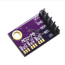
The primary component in this project is the PCA9685 module, which is responsible for generating PWM signals to control the servos. Each servo is connected to one of the 16 channels on the PCA9685, allowing for independent control. The module communicates with the Arduino using I2C protocol, requiring only two wires: SDA and SCL.
In addition to the PCA9685, you'll need an Arduino board, 16 servo motors, and an external power supply. The external power supply is crucial because the Arduino alone may not provide enough current to power all servos simultaneously. Each servo typically operates at 5V, so ensure your power supply matches this requirement.
Datasheet Details
| Manufacturer | NXP Semiconductors |
|---|---|
| Part number | PCA9685 |
| Logic/IO voltage | 2.3 - 5.5 V |
| Supply voltage | 5 V |
| Output current (per channel) | 25 mA |
| PWM frequency guidance | 60 Hz |
| Input logic thresholds | 0.3VCC (low) / 0.7VCC (high) |
| Voltage drop / RDS(on) / saturation | – |
| Thermal limits | – |
| Package | TSSOP-28 / VQFN-28 |
| Notes / variants | – |
- Connect an external 5V power supply for the servos.
- Use I2C for communication, connecting SDA to A4 and SCL to A5 on the Arduino.
- Ensure all grounds are common between the Arduino and the PCA9685.
- Adjust pulse widths according to the specific servos used.
- Maintain proper cooling for the PCA9685 if powering many servos simultaneously.
Wiring Instructions
To wire the PCA9685 module to the Arduino and servo motors, start by connecting the external 5V power supply to the V+ terminal of the PCA9685. Connect the ground of the power supply to the ground terminal of the PCA9685 as well as to the Arduino's ground.
Next, connect the SDA and SCL pins from the PCA9685 to the corresponding pins on the Arduino (SDA to A4 and SCL to A5). Each servo motor will have three wires: ground (usually black or brown), VCC (typically red), and signal (often yellow or white). Connect the ground wire of each servo to the ground terminal of the PCA9685, the VCC wire to the V+ terminal, and the signal wire to the respective channels (0-15) on the PCA9685. Make sure to connect the signal wire in the correct order for each servo.
Code Examples & Walkthrough
We'll now go through the code that controls the servo motors one by one. The code begins by importing the necessary libraries for I2C communication and the PCA9685 module. The following excerpt initializes the PCA9685 object:
#include
#include

Adafruit_PWMServoDriver pwm = Adafruit_PWMServoDriver(); // Initialize PCA9685
In the setup function, we initialize the serial monitor and set the PWM frequency for the servos:
void setup() {
  Serial.begin(9600); // Start serial communication
  pwm.begin(); // Initialize PCA9685
  pwm.setPWMFreq(60); // Set frequency to 60 Hz for servos
}
The main loop contains two nested loops: the outer loop iterates through each of the 16 servos, while the inner loop gradually changes the angle from 0 to 180 degrees:
void loop() {
  for(int i=0; i<16; i++) {
    for(int angle = 0; angle<181; angle += 10) {
      delay(50); // Wait for servo to move
      pwm.setPWM(i, 0, angleToPulse(angle)); // Set servo position
    }
  }
  delay(1000); // Wait before repeating
}
This structure allows each servo to move to its designated angle in increments of 10 degrees, providing smooth transitions. The function angleToPulse(int ang) converts angle values into pulse widths appropriate for the servos:
int angleToPulse(int ang) {
   int pulse = map(ang, 0, 180, SERVOMIN, SERVOMAX); // Map angle to pulse width
   return pulse; // Return pulse width
}
This function is essential for translating the desired angle into a PWM signal that the PCA9685 can understand and transmit to the servos. For further details, remember that the full code loads below the article.
Demonstration / What to Expect
Once everything is wired correctly and the code is uploaded, you should see each servo moving to its respective angles one after the other. If you encounter any issues, double-check your connections and ensure that you have a stable power supply for the servos. If the servos are not responding as expected, verify the PWM signals being sent through the PCA9685.
Video Timestamps
- 00:00 Details of the module with chip PCA9685
- 06:14 Adding library needed for the PCA9685
- 07:14 Loading the example code
- 07:35 Code explained
- 11:31 Simplified Arduino code for PCA9685
- 12:00 Finding minimum and maximum value for your servo
- 18:27 Mapping pulse angle to pulse width
- 20:05 Creating separate method for mapping
- 20:55 Using for loop to test all angles for mapping
This tutorial is part of: Controlling 16 or 32 Servo motor with PCA9685
- Arduino Code and Video for PCA9685 16-Channel 12-Bit Servo Controller V1
- Controlling 16 Servo Motors Using a PCA9685 Module and Arduino V2 Sketch: Individual Servo Control
- Controlling 16 Servo Motors Using a PCA9685 Module and Arduino V2 Sketch #3: All Servos Together
- Controlling a 32 Servo Motor Using a PCA9685 Module and Arduino V3 Sketch #1: All Servos Together
- Controlling a 32 Servo Motor Using a PCA9685 Module and an ESP32 V4
- Control 32 Servos over Wi-Fi Using ESP32 and PCA9685 via Desktop or Mobile Phone V5
/*
 * Original source: https://github.com/adafruit/Adafruit-PWM-Servo-Driver-Library
 * PCA9685 Video V2, Arduino Code-1
 * This is the Arduino code PAC6985 16 channel servo controller
 * watch the video for details (V1) and demo http://youtu.be/y8X9X10Tn1k
 *  This code is #1 for V2 Video Watch the video :https://youtu.be/bal2STaoQ1M
get this code and wiring from https://robojax.com/RTJ243
 *  I have got 3 codes as follow:
   #1-Arduino Code to run one by one all servos from 0 to 180°
   #2-Arduino Code to control specific servos with specific angle
   #3-Arduino Code to run 2 or all servos at together

 * Written/updated by Ahmad Shamshiri for Robojax Video channel www.Robojax.com
 * Date: Dec 16, 2017, in Ajax, Ontario, Canada

 * Watch video for this code:
 *
 * Related Videos
V5 video of PCA9685 32 Servo with ESP32 with WiFi https://youtu.be/bvqfv-FrrLM
V4 video of PCA9685 32 Servo with ESP32 (no WiFi): https://youtu.be/JFdXB8Za5Os
V3 video of PCA9685 how to control 32 Servo motors https://youtu.be/6P21wG7N6t4
V2 Video of PCA9685 3 different ways to control Servo motors: https://youtu.be/bal2STaoQ1M
V1 Video introduction to PCA9685 to control 16 Servo  https://youtu.be/y8X9X10Tn1k

 * Disclaimer: this code is "AS IS" and for educational purpose only.
 * this code has been downloaded from https://robojax.com


or make donation using PayPal http://robojax.com/L/?id=64

 *  * This code is "AS IS" without warranty or liability. Free to be used as long as you keep this note intact.*
 * This code has been download from Robojax.com
    This program is free software: you can redistribute it and/or modify
    it under the terms of the GNU General Public License as published by
    the Free Software Foundation, either version 3 of the License, or
    (at your option) any later version.

    This program is distributed in the hope that it will be useful,
    but WITHOUT ANY WARRANTY; without even the implied warranty of
    MERCHANTABILITY or FITNESS FOR A PARTICULAR PURPOSE.  See the
    GNU General Public License for more details.

    You should have received a copy of the GNU General Public License
    along with this program.  If not, see <https://www.gnu.org/licenses/>.
 */

/***************************************************
  This is an example for our Adafruit 16-channel PWM & Servo driver
  Servo test - this will drive 16 servos, one after the other

  Pick one up today in the adafruit shop!
  ------> http://www.adafruit.com/products/815

  These displays use I2C to communicate, 2 pins are required to
  interface. For Arduino UNOs, thats SCL -> Analog 5, SDA -> Analog 4

  Adafruit invests time and resources providing this open source code,
  please support Adafruit and open-source hardware by purchasing
  products from Adafruit!

  Written by Limor Fried/Ladyada for Adafruit Industries.
  BSD license, all text above must be included in any redistribution
 ****************************************************/

#include <Wire.h>
#include <Adafruit_PWMServoDriver.h>

// called this way, it uses the default address 0x40
Adafruit_PWMServoDriver pwm = Adafruit_PWMServoDriver();
// you can also call it with a different address you want
//Adafruit_PWMServoDriver pwm = Adafruit_PWMServoDriver(0x41);

// Depending on your servo make, the pulse width min and max may vary, you
// want these to be as small/large as possible without hitting the hard stop
// for max range. You'll have to tweak them as necessary to match the servos you
// have!
// Watch video V1 to understand the two lines below: http://youtu.be/y8X9X10Tn1k
#define SERVOMIN  125 // this is the 'minimum' pulse length count (out of 4096)
#define SERVOMAX  575 // this is the 'maximum' pulse length count (out of 4096)

// our servo # counter
uint8_t servonum = 0;

void setup() {
  Serial.begin(9600);
  Serial.println("16 channel Servo test!");

  pwm.begin();

  pwm.setPWMFreq(60);  // Analog servos run at ~60 Hz updates

  //yield();
}

// the code inside loop() has been updated by Robojax
void loop() {

//watch video for details: https://youtu.be/bal2STaoQ1M
for(int i=0; i<16; i++)
  {
    for( int angle =0; angle<181; angle +=10){
      delay(50);
        pwm.setPWM(i, 0, angleToPulse(angle) );
        // see YouTube video for details (robojax)

    }

  }

  // robojax PCA9865 16 channel Servo control
  delay(1000);// wait for 1 second

}

/*
/* angleToPulse(int ang)
 * @brief gets angle in degree and returns the pulse width
 * @param "ang" is integer representing angle from 0 to 180
 * @return returns integer pulse width
 * Usage to use 65 degree: angleToPulse(65);
 * Written by Ahmad Shamshiri on Sep 17, 2019.
 * in Ajax, Ontario, Canada
 * www.Robojax.com
 */

int angleToPulse(int ang){
   int pulse = map(ang,0, 180, SERVOMIN,SERVOMAX);// map angle of 0 to 180 to Servo min and Servo max
   Serial.print("Angle: ");Serial.print(ang);
   Serial.print(" pulse: ");Serial.println(pulse);
   return pulse;
}/*
* Original sourse: https://github.com/adafruit/Adafruit-PWM-Servo-Driver-Library
* PCA9685 Video V2, Arduino Code-2
* This is the Arduino code PAC6985 16 channel servo controller
* watch the video for details (V1) and demo http://youtu.be/y8X9X10Tn1k
* This code is #2 for V2 Video Watch the video :https://youtu.be/bal2STaoQ1M
get codes and wring from https://robojax.com/RTJ243
* I have got 3 codes as follow:
#1-Arduino Code to run one by one all servos from 0 to 180°
#2-Arduino Code to control specific servos with specific angle
#3-Arduino Code to run 2 or all servos at together
*
* Written/updated by Ahmad Shamshiri for Robojax Video channel www.Robojax.com
* Date: Dec 16, 2017, in Ajax, Ontario, Canada
* Permission granted to share this code given that this
* note is kept with the code.
* Disclaimer: this code is "AS IS" and for educational purpose only.
* this code has been downloaded from https://robojax.com
* Watch video for this code:
*
* Related Videos
V5 video of PCA9685 32 Servo with ESP32 with WiFi https://youtu.be/bvqfv-FrrLM
V4 video of PCA9685 32 Servo with ESP32 (no WiFi): https://youtu.be/JFdXB8Za5Os
V3 video of PCA9685 how to control 32 Servo motors https://youtu.be/6P21wG7N6t4
V2 Video of PCA9685 3 different ways to control Servo motors: https://youtu.be/bal2STaoQ1M
V1 Video introduction to PCA9685 to control 16 Servo https://youtu.be/y8X9X10Tn1k
* Get this code and other Arduino codes from Robojax.com
Learn Arduino step by step in structured course with all material, wiring diagram and library
all in once place. Purchase My course on Udemy.com http://robojax.com/L/?id=62
****************************
Get early access to my videos via Patreon and have your name mentioned at end of very
videos I publish on YouTube here: http://robojax.com/L/?id=63 (watch until end of this video to list of my Patrons)
****************************
or make donation using PayPal http://robojax.com/L/?id=64
* * This code is "AS IS" without warranty or liability. Free to be used as long as you keep this note intact.*
* This code has been download from Robojax.com
This program is free software: you can redistribute it and/or modify
it under the terms of the GNU General Public License as published by
the Free Software Foundation, either version 3 of the License, or
(at your option) any later version.
This program is distributed in the hope that it will be useful,
but WITHOUT ANY WARRANTY; without even the implied warranty of
MERCHANTABILITY or FITNESS FOR A PARTICULAR PURPOSE. See the
GNU General Public License for more details.
You should have received a copy of the GNU General Public License
along with this program. If not, see <https://www.gnu.org/licenses/>.
*/
#include <Wire.h>
#include <Adafruit_PWMServoDriver.h>
// called this way, it uses the default address 0x40
Adafruit_PWMServoDriver pwm = Adafruit_PWMServoDriver();
// you can also call it with a different address you want
//Adafruit_PWMServoDriver pwm = Adafruit_PWMServoDriver(0x41);
// Depending on your servo make, the pulse width min and max may vary, you
// want these to be as small/large as possible without hitting the hard stop
// for max range. You'll have to tweak them as necessary to match the servos you
// have!
// Watch video V1 to understand the two lines below: http://youtu.be/y8X9X10Tn1k
#define SERVOMIN 125 // this is the 'minimum' pulse length count (out of 4096)
#define SERVOMAX 575 // this is the 'maximum' pulse length count (out of 4096)
// our servo # counter
uint8_t servonum = 0;
void setup() {
Serial.begin(9600);
Serial.println("16 channel Servo test!");
pwm.begin();
pwm.setPWMFreq(60); // Analog servos run at ~60 Hz updates
//yield();
}
// the code inside loop() has been updated by Robojax
void loop() {
//watch video for details: https://youtu.be/bal2STaoQ1M
for(int i=0; i<16; i++)
{
for( int angle =0; angle<181; angle +=10){
delay(50);
pwm.setPWM(5, 0, angleToPulse(angle) );
pwm.setPWM(8, 0, angleToPulse(angle) );
pwm.setPWM(15, 0, angleToPulse(angle) );
}
}
// robojax PCA9865 16 channel Servo control
delay(1000);
}
/*
* angleToPulse(int ang)
* gets angle in degree and returns the pulse width
* also prints the value on seial monitor
* written by Ahmad Shamshiri for Robojax, Robojax.com
*/
int angleToPulse(int ang){
int pulse = map(ang,0, 180, SERVOMIN,SERVOMAX);// map angle of 0 to 180 to Servo min and Servo max
Serial.print("Angle: ");Serial.print(ang);
Serial.print(" pulse: ");Serial.println(pulse);
return pulse;
}Resources & references
No resources yet.
Files📁
No files available.