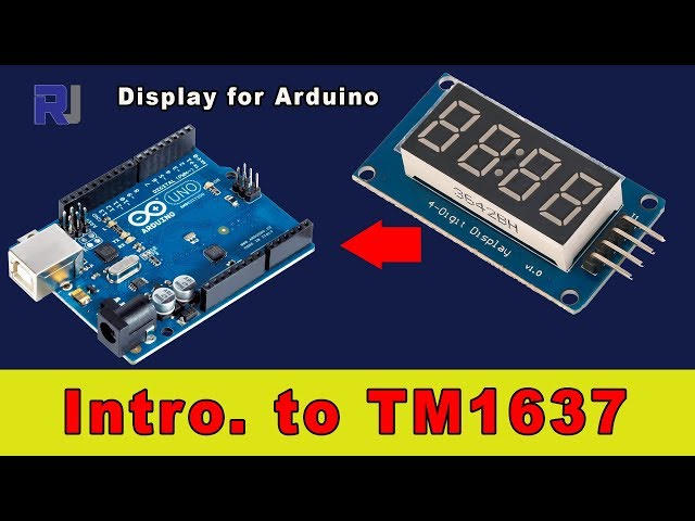
Using a TM1637 4-Digit 7-Segment Display with Arduino
In this tutorial, we will learn how to use the TM1637 4-digit 7-segment display with an Arduino. This display can be utilized to show numbers, counters, or any other numerical data. By the end of the project, you will have a functioning display that can count from 0 to 500 and demonstrate various features such as brightness adjustment.

For this project, we will be connecting the TM1637 display to the Arduino using just a few wires. The display has four pins: VCC, GND, DIO, and CLK. VCC connects to the 5V power supply, while GND connects to the ground. The DIO pin will be connected to digital pin 3 of the Arduino, and the CLK pin will be connected to digital pin 2. This setup allows the Arduino to communicate with the display easily.
To see the practical implementation, make sure to follow along with the video (in video at 00:00) for a visual guide.
Hardware Explained
The TM1637 is a versatile 7-segment display driver that allows for easy control of 4-digit displays. It is controlled using a two-wire interface, which consists of a data pin (DIO) and a clock pin (CLK). This makes it simple to connect to microcontrollers like Arduino without the need for additional components.
The display can show decimal numbers and supports brightness control, making it suitable for a variety of applications such as counters, clocks, and timers. Its compact design and ease of use make it a popular choice among hobbyists and professionals alike.
Datasheet Details
| Manufacturer | Titan Micro Electronics |
|---|---|
| Part number | TM1637 |
| Logic/IO voltage | 5 V |
| Supply voltage | 3.3 V - 5.5 V |
| Output current (per segment) | 20 mA |
| PWM frequency guidance | N/A |
| Input logic thresholds | 0.3 VCC (low), 0.7 VCC (high) |
| Voltage drop / RDS(on) / saturation | 2.5 V (typ.) |
| Thermal limits | 125 °C |
| Package | 16-pin DIP |
- Ensure that VCC is connected to a stable 5V source to avoid display malfunction.
- Use current limiting resistors if necessary to prevent damage to segments.
- Keep wiring short to minimize noise and interference.
- Always double-check pin connections to prevent reverse polarity.
- Adjust brightness levels using the
setBrightnessfunction for optimal visibility.
Wiring Instructions


To wire the TM1637 display, first connect the VCC pin to the 5V output of the Arduino. Next, connect the GND pin to one of the ground pins on the Arduino. For the data communication, connect the DIO pin of the display to digital pin 3 on the Arduino, and the CLK pin to digital pin 2. This simple setup allows the Arduino to communicate with the display effectively.
Ensure that you have secure connections to avoid any loose wiring issues. In the video, alternative wiring configurations are shown, but the provided connections are the most straightforward for basic operation (in video at 01:30).
Code Examples & Walkthrough
The provided code initializes the display and sets up the necessary configurations. The key identifiers in the code include CLK and DIO, which are defined as digital pins 2 and 3, respectively. The brightness of the display is set using the setBrightness function.
#define CLK 2
#define DIO 3
TM1637Display display(CLK, DIO);
void setup() {
display.setBrightness(0x0f); // Set maximum brightness
}
This code excerpt shows the initialization of the display and the setting of maximum brightness. Next, the loop function demonstrates how to display various numbers.

void loop() {
uint8_t data[] = { 0x0, 0x0, 0x0, 0x0 };
display.setSegments(data); // Clear the display
display.showNumberDec(23, false, 2, 1); // Show number 23
delay(TEST_DELAY);
}
Here, the display is cleared, and the number 23 is shown. The function showNumberDec takes parameters to control the number displayed and its formatting. The loop continues to display numbers up to 500.
for(int i=0; i<=500; i++) {
display.showNumberDec(i); // Show numbers from 0 to 500
}
This code snippet illustrates a simple counter that displays numbers from 0 to 500 on the TM1637 display. The display will update continuously until it reaches 500, then it will loop back to 0. The full code is available below the article for your reference.
Demonstration / What to Expect
Once everything is wired and the code is uploaded, the display should show the numbers sequentially from 0 to 500. It will also demonstrate various brightness settings and clear the screen appropriately between updates. Be cautious of reversed polarity, as this can damage the display. You can confirm functionality by observing the display during the video (in video at 04:00).
Video Timestamps
- 00:00 - Introduction to the TM1637 Display
- 01:30 - Wiring Instructions
- 02:45 - Code Walkthrough
- 04:00 - Demonstration of the Display
资源与参考
尚无可用资源。
文件📁
Arduino 库(zip 格式)
-
TM1637 Arduino Library
TM1637_library.zip1.36 MB
数据手册 (pdf)
-
TM1637 数据表
/download/datasheet/robojax_TM1637_datasheet.pdf0.67 MB
用户手册
-
TM1637 显示器手册
robojax-TM1637_display_manual.pdf0.31 MB