Controlling Multiple DC Motors Using a BTS7960 Module with Arduino
In this tutorial, we will explore how to control multiple DC motors using the BTS7960 module with an Arduino. The BTS7960 is a powerful motor driver capable of handling high currents and allows for precise control of motor direction and speed through PWM (Pulse Width Modulation). By the end of this project, you will have a working setup that can control two DC motors, rotating them in both clockwise and counterclockwise directions. This tutorial will guide you through the hardware setup, wiring instructions, and the code needed to operate the motors. For a clearer understanding of the entire process, make sure to check out the accompanying video (in video at 00:00).
Hardware Explained
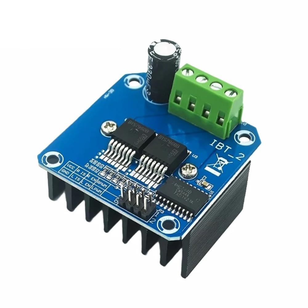
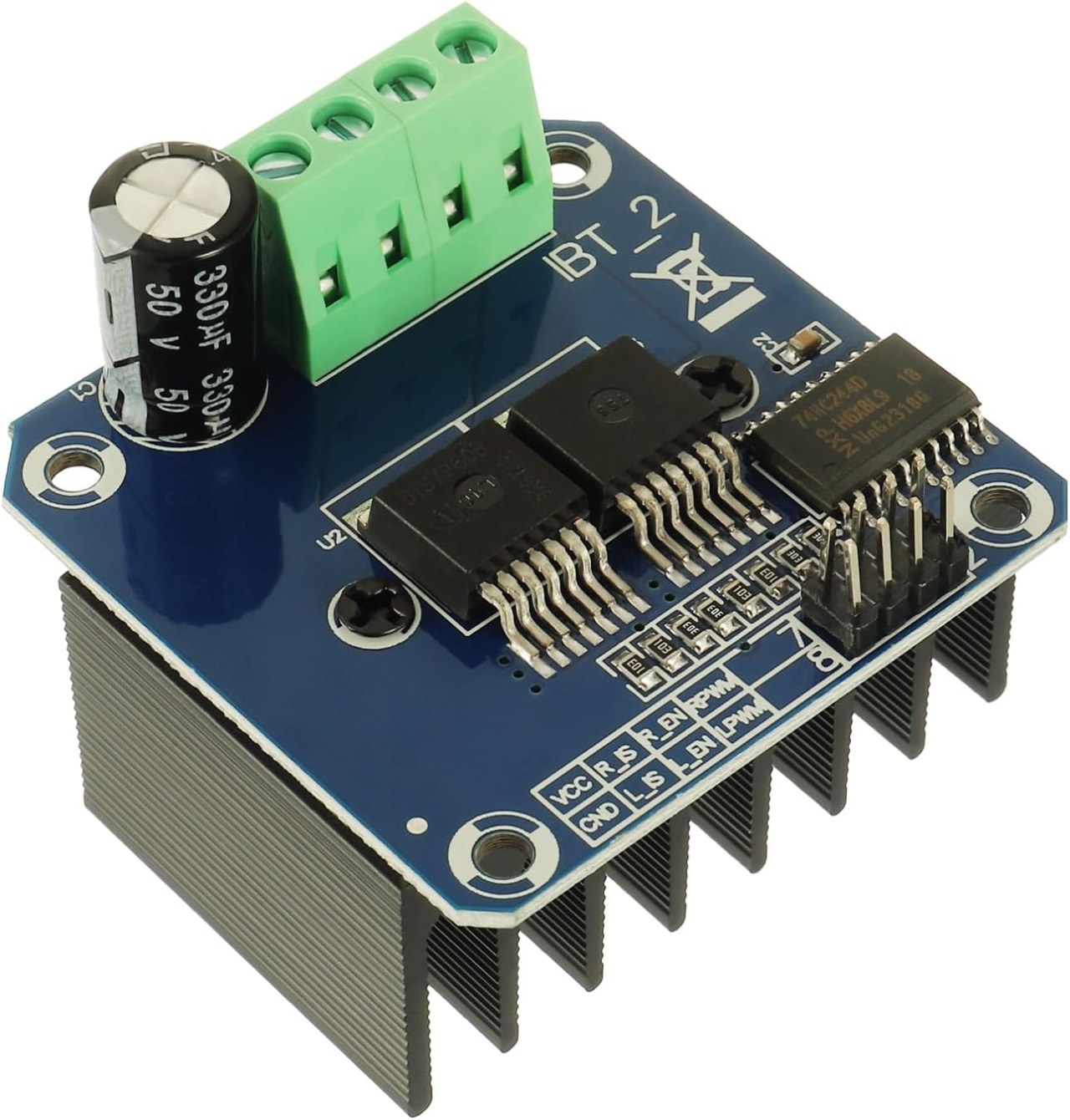
The primary component of this project is the BTS7960 motor driver module. This module includes two H-bridge drivers that can control the direction of the motors by switching the polarity of the voltage applied to the motor. Each driver can handle up to 43A of current, which makes it suitable for high-power applications. The module also features built-in protection against over-temperature and over-current situations. In addition to the BTS7960, you will need an Arduino board for controlling the motors. The Arduino sends PWM signals to the motor driver, allowing you to adjust the speed and direction of the motors. The connections between the Arduino and the BTS7960 module are crucial, as they dictate how the motors will respond to the signals.
Datasheet Details
| Manufacturer | Infineon Technologies |
|---|---|
| Part number | BTS7960 |
| Logic/IO voltage | 3.3 V to 5 V |
| Supply voltage | 5–40 V |
| Output current (per channel) | 43 A max |
| Peak current (per channel) | 60 A |
| PWM frequency guidance | 5–25 kHz |
| Input logic thresholds | 0.8 V (high), 0.3 V (low) |
| Voltage drop / RDS(on) / saturation | 16 mΩ |
| Thermal limits | 150 °C max |
| Package | TO-263 |
| Notes / variants | Dual H-bridge configuration |
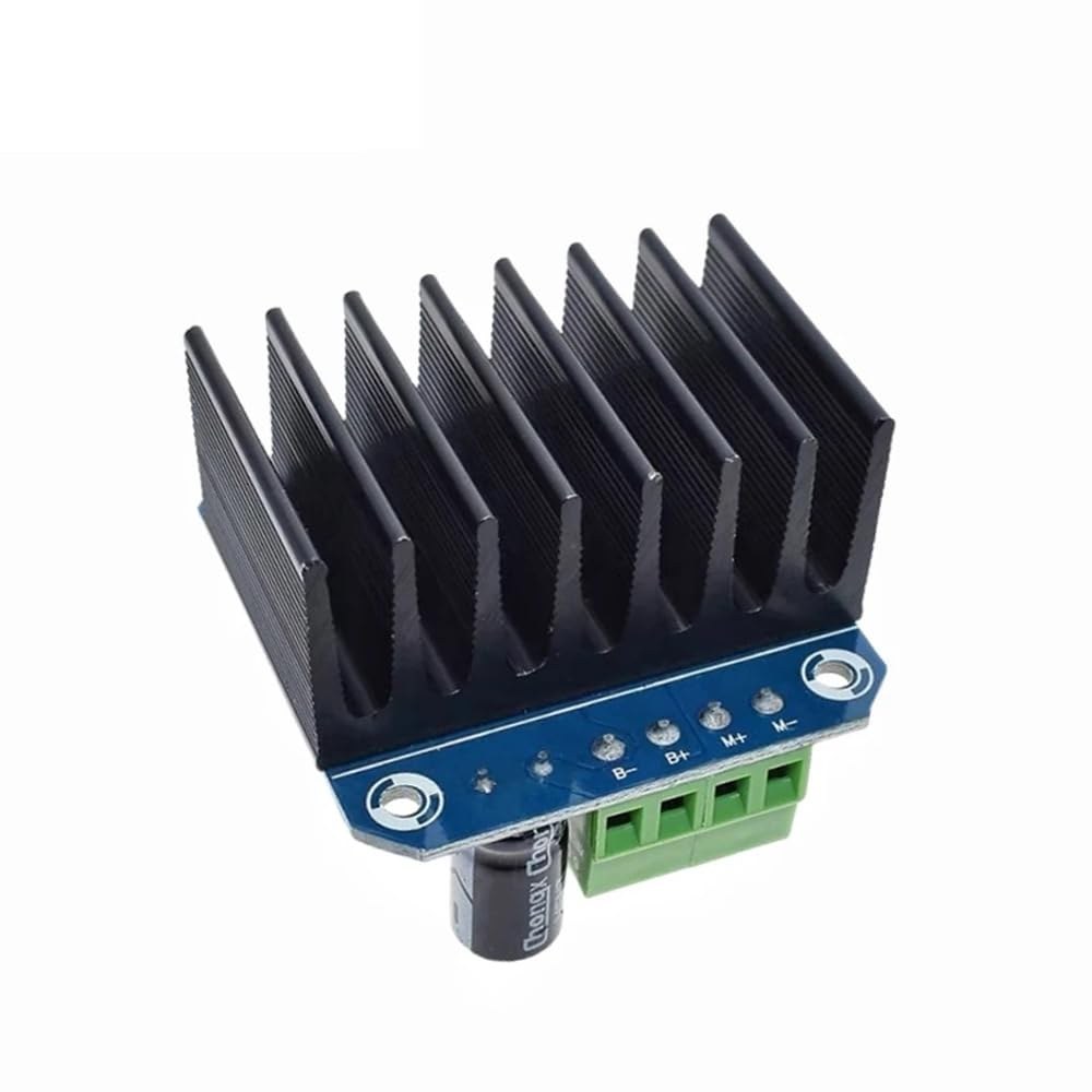
- Ensure proper heat sinking when operating at high currents.
- Use appropriate wire gauge for power connections.
- Double-check pin mappings between the Arduino and BTS7960.
- Implement current limiting to prevent damage to the module.
- Use decoupling capacitors near the power supply for stability.
Wiring Instructions

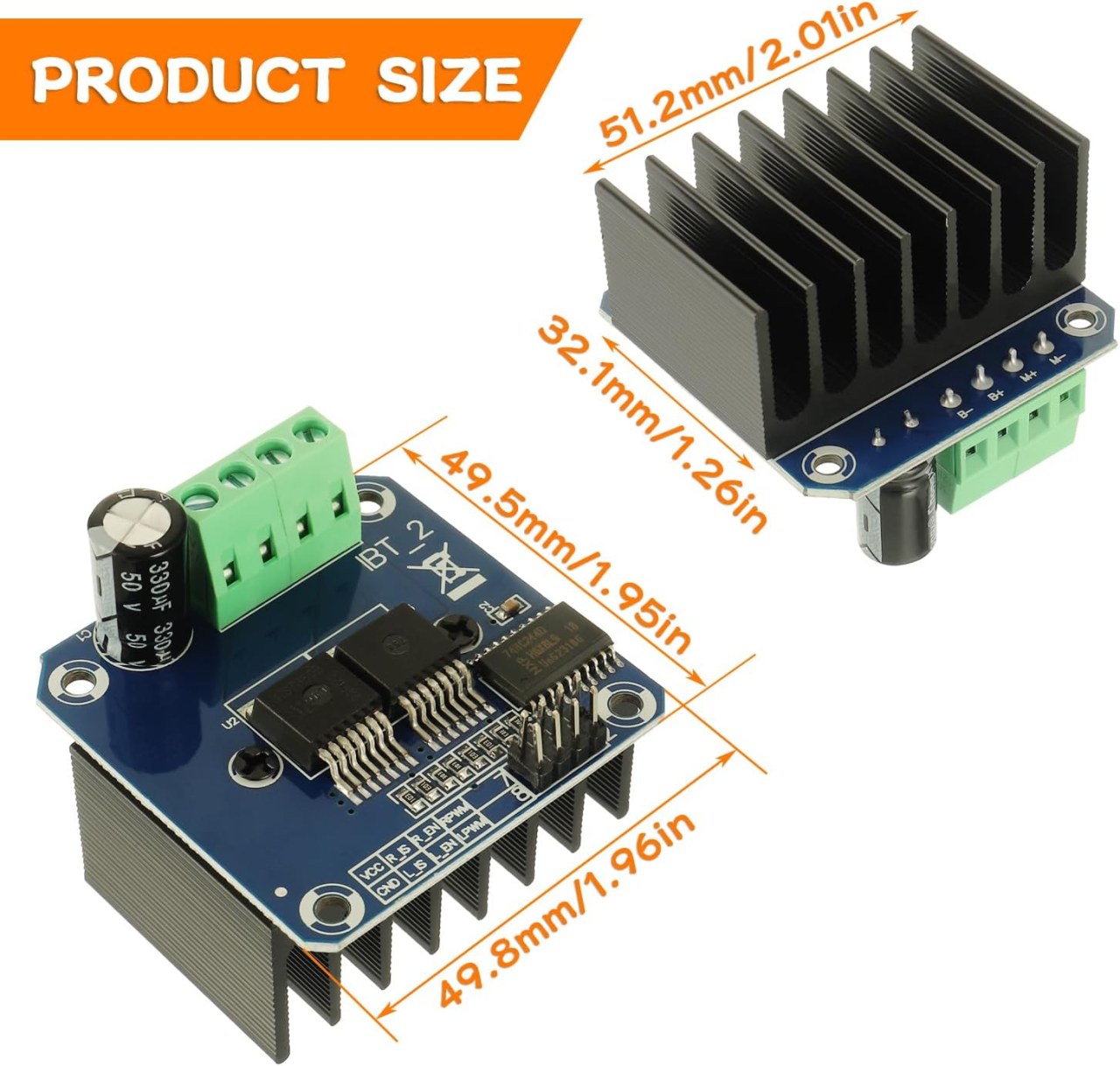
To wire the BTS7960 module to the Arduino, follow these connections carefully: 1. **Power Connections**: Connect the positive terminal of your power source to the B+ terminal on the BTS7960 module, and the negative terminal to the B- terminal. Ensure that the power source matches the voltage requirements of your motors. 2. **Motor Connections**: Connect the motor wires to the M+ and M- terminals on the module. This will enable the module to control the motor. 3. **Arduino Pins**: Connect the following pins on the Arduino to the BTS7960 module: - Pin 3 (RPWM) to the RPWM pin on the module. - Pin 4 (R_EN) to the R_EN pin on the module. - Pin 5 (R_IS) to the R_IS pin on the module. - Pin 6 (LPWM) to the LPWM pin on the module. - Pin 7 (L_EN) to the L_EN pin on the module. - Pin 8 (L_IS) to the L_IS pin on the module. 4. **Ground Connections**: Connect the ground pin of the Arduino to the ground pin on the BTS7960 module to ensure a common reference for the signals. Make sure all connections are secure to prevent any unexpected behavior during operation.
Install required library
To install the robojax_BTS7960_motor_driver_library in the Arduino IDE, first download the library's ZIP file from the provided link. With the file saved, open your Arduino IDE and navigate to Sketch > Include Library > Add .ZIP Library.... In the file selection dialog, browse to the downloaded ZIP file, select it, and click "Open". The IDE will then install the library. You can confirm a successful installation by checking the File > Examples menu, where a new category named "Robojax BTS7960 Motor Driver Library" should appear. You can now include the library header in your code with #include <RobojaxBTS7960.h>.
Code Examples & Walkthrough
The following code snippets demonstrate how to set up and control the motors using the BTS7960 module. The initial setup defines the pins connected to the motors and initializes the motor objects:
// pins for motor 1
#define RPWM_1 3
#define R_EN_1 4
#define R_IS_1 5
#define LPWM_1 6
#define L_EN_1 7
#define L_IS_1 8

// pins for motor 2
#define RPWM_2 9
#define R_EN_2 10
#define R_IS_2 12
#define LPWM_2 11
#define L_EN_2 A0
#define L_IS_2 A1

#include
RobojaxBTS7960 motor1(R_EN_1, RPWM_1, R_IS_1, L_EN_1, LPWM_1, L_IS_1, debug);
RobojaxBTS7960 motor2(R_EN_2, RPWM_2, R_IS_2, L_EN_2, LPWM_2, L_IS_2, debug);
This section of code sets up the pin definitions and creates instances of the `RobojaxBTS7960` class for both motors. The `setup()` function initializes the motors and the serial monitor:
void setup() {
  Serial.begin(9600); // setup Serial Monitor
  motor1.begin();
  motor2.begin();
}
Here, the `motor.begin()` method prepares each motor for operation, allowing you to control them in the `loop()` function. In the `loop()` function, you can control the motors with commands like this:
void loop() {
   motor1.rotate(100, CW); // run motor 1 at 100% speed CW
   delay(5000); // run for 5 seconds
   motor1.stop(); // stop motor 1
   delay(3000); // stop for 3 seconds
   motor2.rotate(100, CCW); // run motor 2 at 100% speed CCW
   delay(5000); // run for 5 seconds
   motor2.stop(); // stop motor 2
   delay(3000); // stop for 3 seconds
}
This section shows how to rotate the motors in both directions and control their speed. The full code is loaded below the article for your reference.
Demonstration / What to Expect
Upon completing the wiring and uploading the code, you should observe the motors rotating in both clockwise and counterclockwise directions. The code will run each motor at full speed for five seconds, stop for three seconds, and repeat the process. Watch for any potential issues such as reversed connections or insufficient power supply. If you encounter problems, double-check your wiring and ensure that the power source is adequate (in video at 00:00).
Video Timestamps
- 00:00 Start
- 00:48 Hardware Explained
- 04:06 Datasheet viewed
- 07:07 Wiring Explained
- 09:00 Code explained
- 14:33 Demonstration
- 16:47 Maximum current test
- 19:25 Thermal image
- 19:27 Different code test
Изображения
++
/*
* This is the Arduino code for the BTS7960 DC motor driver.
Using this code, you can control more than one motor to rotate in both directions: clockwise (CW)
and counter-clockwise (CCW).
📚⬇️ Download and resource page for this video https://robojax.com/RJT169
📚⬇️ Download and resource page https://robojax.com/RJT170


Written by Ahmad Shamshiri for Robojax.com on
July 16, 2020 in Ajax, Ontario, Canada.

Watch video instructions for this code:  https://youtu.be/PUL5DZ9TA2o


BTS7960B
If you found this tutorial helpful, please support me so I can continue creating
content like this. You can support me on Patreon: http://robojax.com/L/?id=63

or make a donation using PayPal: http://robojax.com/L/?id=64

 * This code has been downloaded from Robojax.com
    This program is free software: you can redistribute it and/or modify
    it under the terms of the GNU General Public License as published by
    the Free Software Foundation, either version 3 of the License, or
    (at your option) any later version.

    This program is distributed in the hope that it will be useful,
    but WITHOUT ANY WARRANTY; without even the implied warranty of
    MERCHANTABILITY or FITNESS FOR A PARTICULAR PURPOSE.  See the
    GNU General Public License for more details.

    You should have received a copy of the GNU General Public License
    along with this program.  If not, see <https://www.gnu.org/licenses/>.

*/

// pins for motor 1
#define RPWM_1 3 // define pin 3 for RPWM pin (output)
#define R_EN_1 4 // define pin 2 for R_EN pin (input)
#define R_IS_1 5 // define pin 5 for R_IS pin (output)

#define LPWM_1 6 // define pin 6 for LPWM pin (output)
#define L_EN_1 7 // define pin 7 for L_EN pin (input)
#define L_IS_1 8 // define pin 8 for L_IS pin (output)
// motor 1 pins end here

// pins for motor 2
#define RPWM_2 9 // define pin 9 for RPWM pin (output)
#define R_EN_2 10 // define pin 10 for R_EN pin (input)
#define R_IS_2 12 // define pin 12 for R_IS pin (output)

#define LPWM_2 11 // define pin 11 for LPWM pin (output)
#define L_EN_2 A0 // define pin 7 for L_EN pin (input)
#define L_IS_2 A1 // define pin 8 for L_IS pin (output)
// motor 2 pins end here


#define CW 1 //
#define CCW 0 //
#define debug 1 //

#include <RobojaxBTS7960.h>
RobojaxBTS7960 motor1(R_EN_1,RPWM_1,R_IS_1, L_EN_1,LPWM_1,L_IS_1,debug);//define motor 1 object
RobojaxBTS7960 motor2(R_EN_2,RPWM_2,R_IS_2, L_EN_2,LPWM_2,L_IS_2,debug);//define motor 2 object and the same way for other motors

void setup() {
  // BTS7960 Motor Control Code by Robojax.com 20190622
  Serial.begin(9600);// setup Serial Monitor to display information

   motor1.begin();
   motor2.begin();

    // BTS7960 Motor Control Code by Robojax.com 20190622
}

void loop() {
   // BTS7960 Motor Control Code by Robojax.com 20190622
    motor1.rotate(100,CW);// run motor 1 with 100% speed in CW direction
    delay(5000);//run for 5 seconds
    motor1.stop();// stop the motor 1
    delay(3000);// stop for 3 seconds
    motor1.rotate(100,CCW);// run motor 1 at 100% speed in CCW direction
    delay(5000);// run for 5 seconds
    motor1.stop();// stop the motor 1
    delay(3000);  // stop for 3 seconds

    motor2.rotate(100,CW);// run motor 2 with 100% speed in CW direction
    delay(5000);//run for 5 seconds
    motor2.stop();// stop the motor 2
    delay(3000);// stop for 3 seconds
    motor2.rotate(100,CCW);// run motor 2 at 100% speed in CCW direction
    delay(5000);// run for 5 seconds
    motor2.stop();// stop the motor 2
    delay(3000);  // stop for 3 seconds


  // slowly speed up the motor 1 from 0 to 100% speed
    for(int i=0; i<=100; i++){
        motor1.rotate(i,CCW);
        delay(50);
    }

   // slow down the motor 2 from 100% to 0
    for(int i=100; i>0; i--){
        motor2.rotate(i,CCW);
        delay(50);
    }
    motor2.stop();// stop motor 2
    delay(3000); // stop for 3 seconds
 // BTS7960 more than 1 Motor Control Code by Robojax.com 20190622
}// loop ends
Ресурсы и ссылки
-
ВнешнийBTS7960 Амазон Японияamzn.to
-
ВнешнийBTS7960 на Amazon Italiaamzn.to
-
ВнешнийBTS7960 на Amazon Испанияamzn.to
-
ВнешнийBTS7960 на Amazon Францияamzn.to
-
ВнешнийBTS7960, Amazon Германияamzn.to
-
ВнешнийКупите BTS7960 на Amazonamzn.to
-
ВнешнийКупите BTS7960 на Amazon Канадаamzn.to
-
ВнешнийКупить BTS7960, Amazon UKamzn.to
-
ВнешнийТехнические данные модуля BTS7960 (PDF)handsontec.com
Файлы📁
Библиотеки Arduino (zip)
-
robojax_BTS7960_библиотека_управления_мотором
robojax_BTS7960_motor_driver_library.zip0.10 MB
Технический паспорт (pdf)
-
BTS7960_datasheet
BTS7960_datasheet.pdf0.45 MB
Файл Fritzing
-
BTS7960_драйвер
BTS7960_driver.fzpz0.01 MB