Dieses Tutorial ist Teil von: Relaissteuerung mit Arduino
Hier finden Sie Gruppenvideos zum Thema Staffellauf. Links zu weiteren Videos finden Sie unter diesem Artikel.

Using a TTP223B touch module and relay to control AC/DC loads with an Arduino
In this tutorial, we will explore how to use the TTP223B capacitive touch module alongside a relay to control AC or DC loads with an Arduino. This setup allows for convenient touch-based activation of devices such as light bulbs or other electrical components. You will learn how to wire the components, write the Arduino code, and adjust the timing for how long the load remains active after being touched. This is a great project for both beginners and experienced users looking to expand their skills.


Throughout this guide, we will walk you through the essential components, wiring instructions, and the programming required to get this project up and running. You will also learn how to modify the timing for load activation based on your preferences (in video at 10:15). Be sure to check out the accompanying video for a visual demonstration of the process.
Hardware Explained
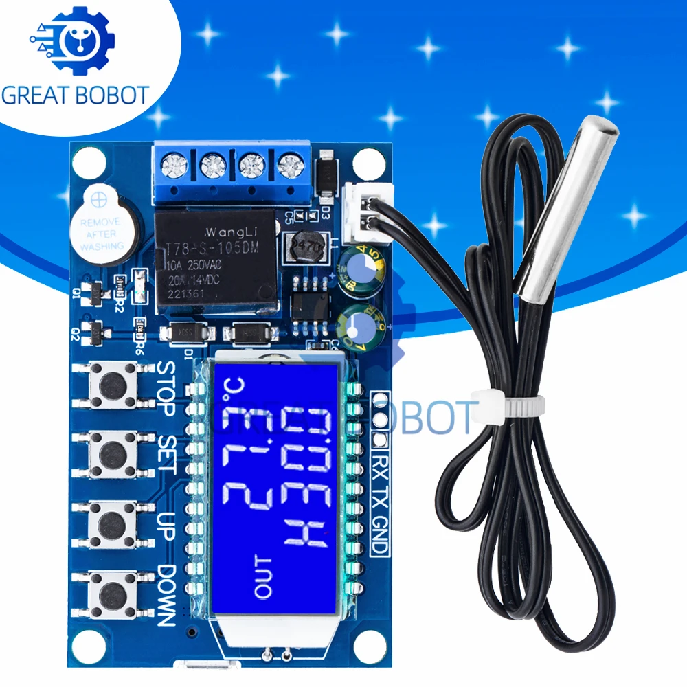
The key components for this project include the TTP223B touch module, a relay, and an Arduino. The TTP223B module detects touch inputs and sends a signal to the Arduino, which can then control the relay. The relay acts as a switch, allowing you to control higher voltage AC or DC loads safely.
The TTP223B chip is made by Taiwan Semiconductor (TONTEK) and module operates on a supply voltage of 2.2V to 5.5V and has three pins: VCC (power), GND (ground), and SIG (signal). When the touchpad is activated, the SIG pin sends a high signal to the Arduino. View datasheet for full details. The relay, on the other hand, requires a control signal from the Arduino to switch the load on or off. This control is achieved through a digital output pin connected to the relay.
Datasheet Details
| Manufacturer | Taiwan Semiconductor (TONTEK) |
|---|---|
| Part number | TTP223B |
| Logic/IO voltage | 2.2 - 5.5 V |
| Supply voltage | 2.2 - 5.5 V |
| Output current (per channel) | 20 mA max |
| Peak current (per channel) | 50 mA max |
| PWM frequency guidance | N/A |
| Input logic thresholds | 0.3 * VCC (low), 0.7 * VCC (high) |
| Voltage drop / RDS(on) / saturation | N/A |
| Thermal limits | N/A |
| Package | TO-220 |
| Notes / variants | Also known as BA6 |
- Ensure proper grounding to avoid false triggering.
- Use a capacitor to filter noise on the touch signal line.
- Verify relay specifications to match load requirements.
- Be cautious with AC connections—ensure proper insulation and safety measures.
- Adjust the timing in the code for desired load activation duration.
Wiring Instructions
To wire the TTP223B touch module and relay with the Arduino, follow these steps:
First, connect the VCC pin of the TTP223B to a 5V power source, either from the Arduino or an external supply. Next, connect the GND pin of the TTP223B to the ground. The SIG pin should be connected to pin 2 on the Arduino, which will read the touch input.
For the relay, connect its VCC pin to the same 5V power source, and connect its GND pin to ground. The control signal pin of the relay should be connected to pin 10 on the Arduino. Ensure that the relay is wired correctly to the load you want to control, with one wire going to the common (COM) pin and the other to the normally open (NO) pin. This setup allows the relay to switch the load on and off based on the Arduino's control signal.
Code Examples & Walkthrough
The following code snippet initializes the setup for the TTP223B touch module and relay. It sets pin modes for input and output, enabling the Arduino to read touch signals and control the relay.
void setup() {
    Serial.begin(9600);
    pinMode(10, OUTPUT); // Relay control pin
    pinMode(2, INPUT);   // Touch input pin
    Serial.println("Robojax Test: TTP223B touch");
}
In the setup, we define pin 10 as an output to control the relay and pin 2 as an input to read the touch signal. A serial monitor is initiated for debugging purposes.
The main loop of the program checks if the touch button is pressed. If it is, the relay is activated, turning on the connected load.
void loop() {
    if(digitalRead(2)) {
        Serial.println("Button Touched");
        digitalWrite(10, LOW); // Turn the relay ON
        delay(LD);
    } else {
        digitalWrite(10, HIGH); // Turn OFF the relay
    }
}
This code continuously reads the state of pin 2. If the touch sensor is activated, it turns the relay on for a specified duration defined by the variable LD. If the sensor is not touched, the relay turns off.
Demonstration / What to Expect
Upon completing the wiring and uploading the code, you should see the connected load (e.g., a light bulb) turn on when you touch the TTP223B module. The duration for which the load remains on is controlled by the LD variable in the code. If you want the load to stay on longer, simply increase the value of LD to the desired duration in milliseconds.
Common pitfalls include incorrect wiring, which could lead to the relay not activating or the touch sensor not responding. Ensure that all connections are secure and that you are using the correct pins as defined in the code. Additionally, be cautious when working with AC loads to avoid electric shock or damage.
Video Timestamps
- 00:00 - Introduction to the project
- 02:30 - Wiring overview
- 05:15 - Code explanation
- 10:15 - Demonstration of the setup
Bilder


Dieses Tutorial ist Teil von: Relaissteuerung mit Arduino
- Arduino-Code und Video für ein zweikanaliges 5V-Relais
- Ein 5V-Relais mit Arduino steuern, um AC- oder DC-Lasten wie eine Glühbirne oder einen Motor zu schalten
- TTP224 4-Channel Touch Sensor to Turn AC/DC Loads with Relay
- Verwendung eines 5V-Relaismoduls (Low-Trigger) mit Arduino
- Verwendung eines MAX6675 K-Typ-Thermoelements mit Relais und Anzeige
- Using a Reed Switch to Control a Relay and AC/DC Loads with an Arduino
- Einen Arduino-Taster verwenden, um ein Relais und eine Wechselstromlampe zu schalten
/*
 * Dies ist der Arduino-Code für den kapazitiven Touch-Schalter TTP223B mit Relais. Der Ausgangspin 10 ist mit dem Relais verbunden. Durch Berühren der Touch-Oberfläche TTP223B oder TTP223N-BA6 wird das Relais eingeschaltet.
 *
 * Geschrieben von Ahmad Nejrabi für Roboja Video. Datum: 4. Dezember 2017, in Ajax, Ontario, Kanada. Erlaubnis zur Weitergabe dieses Codes, sofern dieser Hinweis zusammen mit dem Code aufbewahrt wird. Haftungsausschluss: Dieser Code ist "WIE BESEHEN" und nur für Bildungszwecke.
 */
 int LD = 200; // Schleifenverzögerung. Steuert, wie lange die Lampe nach dem Loslassen AN bleibt.

void setup() {
    Serial.begin(9600);
 // Ausgangspins
    pinMode(10, OUTPUT); // LED für Taste 1


 // Eingabepins
    pinMode(2, INPUT); // Taste 1 Eingangspin 2


    Serial.println("Robojax Test: TTP223B touch");

}

void loop() {

 // Taste 1 Aktion
    if(digitalRead(2)){
      Serial.println("Button Touched");
      digitalWrite(10, LOW); // Schalte die LED ein
      delay(LD);
    }else{
      digitalWrite(10, HIGH); // Schalte die LED aus.
    }


} // Schleife
/*
 * Dies ist der Arduino-Code für den TTP223 kapazitiven Touch-Schalter mit Relais, um eine Wechselstrom- oder Gleichstromlast ein- oder auszuschalten.
 * // 13. Dezember 2017
 * // Geschrieben für das Robojax.com-Video
 * // Verwendung des TTP223-Touchmoduls, um eine Wechselstrom- (oder Gleichstrom-) Last EIN oder AUS zu schalten.
 * // Wenn das Touchpad berührt wird, leuchtet das Licht am Relais und die COM- und NO-Pins werden verbunden.
 * Video ansehen für Details https://youtu.be/YSI1PdSLbt0
 *
 * Geschrieben von Ahmad Nejrabi für RoboJax Video
 * Datum: 4. Dezember 2017, in Ajax, Ontario, Kanada
 * Erlaubnis zur Weitergabe dieses Codes, sofern diese
 * Notiz mit dem Code aufbewahrt wird.
 * Haftungsausschluss: dieser Code ist "WIE BESEHEN" und nur für Bildungszwecke.
 *
 * /
 *
 * // 12. Dezember 2017
 * // Geschrieben für das Robojax.com-Video
 * // Verwendung des TTP223-Touchmoduls, um eine Wechselstrom- (oder Gleichstrom-) Last EIN oder AUS zu schalten.
 * // Wenn das Touchpad berührt wird, leuchtet das Licht am Relais und die COM- und NO-Pins werden verbunden.
 */
int touchPin = 2; // Verbinden Sie den Ausgang von TTP223 mit diesem.
int val = 0;
int relayPin = 10; // Mit dem Relais verbunden


void setup() {
  Serial.begin(9600);
  pinMode(touchPin, INPUT);
  pinMode(relayPin, OUTPUT);

}

void loop() {
  digitalWrite(relayPin, HIGH);
  val = digitalRead(touchPin);
  if(val ==1){
    Serial.println("Touched");
    digitalWrite(relayPin, LOW);

  }
  delay(100);
  Serial.println();
}
/*
 * Dies ist der Arduino-Code für den TTP223 kapazitiven Touch-Schalter mit Relais, um eine AC- oder DC-Last mit Verzögerung zu schalten.
 * // 13. Dezember 2017
 * // Verfasst für das Robojax.com-Video
 * // Verwendung des TTP223-Touch-Moduls, um eine AC- (oder DC-)Last einzuschalten und 5 Sekunden zu warten, bevor sie ausgeschaltet wird
 * // Wenn das Touchpad berührt wird, leuchtet das Licht am Relais auf und die COM- und NO-Pins werden verbunden
 * Siehe das Video für Details: https://youtu.be/YSI1PdSLbt0
 *
 * Verfasst von Ahmad Nejrabi für das RoboJax-Video
 * Datum: 4. Dezember 2017 in Ajax, Ontario, Kanada
 * Genehmigung zur Weitergabe dieses Codes, sofern diese
 * Notiz mit dem Code aufbewahrt wird.
 * Haftungsausschluss: Dieser Code ist "WIE BESEHEN" und nur für Bildungszwecke.
 *
 * /
 *
 * // 12. Dezember 2017
 * // Verfasst für das Robojax.com-Video
 * // Verwendung des TTP223-Touch-Moduls, um eine AC- (oder DC-)Last ein- oder auszuschalten.
 * // Wenn das Touchpad berührt wird, leuchtet das Licht am Relais auf und die COM- und NO-Pins werden verbunden.
 */
int touchPin = 2; // Verbinde den Ausgang von TTP223 damit.
int val = 0;
int relayPin = 10; // Mit Relay verbunden
int wait = 5; // warte 5 Sekunden


void setup() {
  Serial.begin(9600);
  pinMode(touchPin, INPUT);
  pinMode(relayPin, OUTPUT);

}

void loop() {
  digitalWrite(relayPin, HIGH);
  val = digitalRead(touchPin);
  if(val ==1){
    Serial.println("Touched");
    digitalWrite(relayPin, LOW);
    delay(wait*1000);
  }
  delay(100);
  Serial.println();
}
Ressourcen & Referenzen
Noch keine Ressourcen vorhanden.
Dateien📁
Datenblatt (pdf)
-
TTP223-Datenblatt von Taiwan Semiconductor (TONTEK)
TTP223_datasheet.pdf0.27 MB