Controlling a BTS7960 DC Motor Driver Module with an Arduino
In this tutorial, we will learn how to control a BTS7960 DC motor driver module using an Arduino. This setup allows you to control a DC motor's direction and speed using Pulse Width Modulation (PWM). By the end of this tutorial, you'll have a working motor control system that you can easily modify for your own projects. For detailed visual guidance, make sure to check out the video at (in video at 00:00).
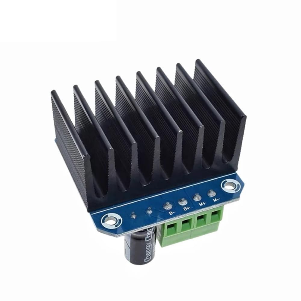
Hardware Explained
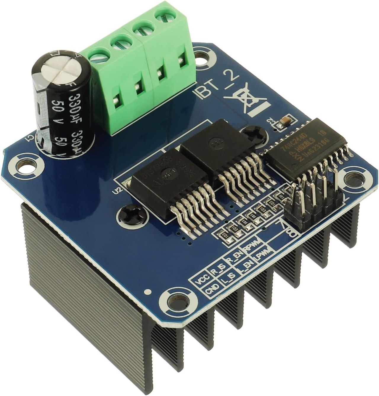
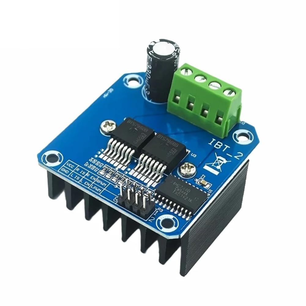
The BTS7960 is a high-current DC motor driver capable of handling up to 43 Amps. It consists of two integrated circuits (ICs) that allow control of a motor in both clockwise (CW) and counterclockwise (CCW) directions. The driver uses PWM signals to vary the speed of the motor, which is essential for applications requiring precise control.
Another important aspect of this module is its built-in current sensing and over-temperature protection features. This helps prevent damage to the motor and driver during operation. The module is powered from an external source, and it also requires a separate 5V supply for its logic circuits.
Datasheet Details
| Manufacturer | Infineon Technologies |
|---|---|
| Part number | BTS7960 |
| Logic/IO voltage | 5 V |
| Supply voltage | 6–27 V |
| Output current (per channel) | 43 A max |
| Peak current (per channel) | 60 A |
| PWM frequency guidance | 25 kHz |
| Input logic thresholds | 0.8 V (high), 0.3 V (low) |
| Voltage drop / RDS(on) / saturation | 16 mΩ |
| Thermal limits | 125 °C max |
| Package | PTO-263-7 |
| Notes / variants | Dual H-Bridge configuration |
- Ensure proper heat sinking for high-current applications.
- Use appropriate wire gauge to handle the maximum current.
- Keep PWM frequency within specified limits for optimal performance.
- Implement decoupling capacitors near power pins to stabilize voltage.
- Monitor temperature during operation to prevent overheating.
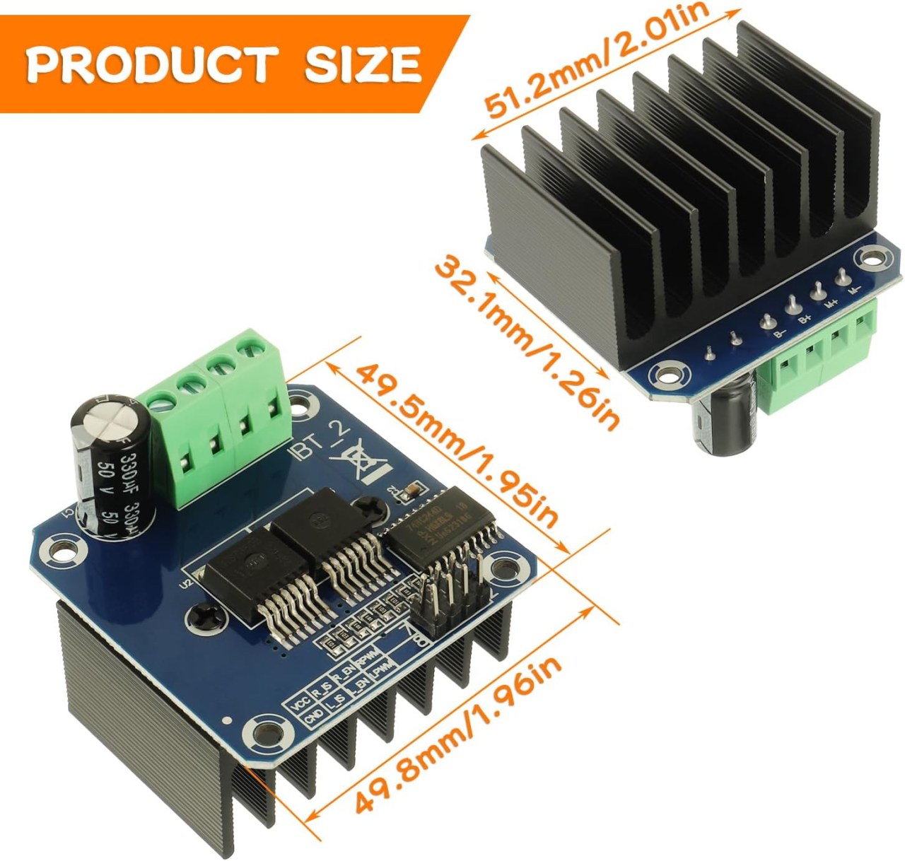
Wiring Instructions

To wire the BTS7960 motor driver module to your Arduino, you'll need to connect the power, ground, control, and motor terminals correctly. Start by connecting the power supply to the module's B+ and B- terminals, ensuring the polarity is correct. The B+ terminal is where the positive supply connects, while B- connects to ground.
Next, connect the motor to the M+ and M- terminals on the module. These will control the direction of the motor. For control pins, connect the Arduino pins to the module as follows: RPWM to pin 3, R_EN to pin 4, R_IS to pin 5, LPWM to pin 6, L_EN to pin 7, and L_IS to pin 8. Make sure to connect the Arduino ground to the module ground as well.
Install required library
To install the robojax_BTS7960_motor_driver_library in the Arduino IDE, first download the library's ZIP file from the provided link. With the file saved, open your Arduino IDE and navigate to Sketch > Include Library > Add .ZIP Library.... In the file selection dialog, browse to the downloaded ZIP file, select it, and click "Open". The IDE will then install the library. You can confirm a successful installation by checking the File > Examples menu, where a new category named "Robojax BTS7960 Motor Driver Library" should appear. You can now include the library header in your code with #include <RobojaxBTS7960.h>.
Code Examples & Walkthrough
The Arduino code for controlling the BTS7960 motor driver begins with defining the necessary pins. For instance, the pin for the right PWM signal is defined as RPWM and set to pin 3. Additionally, the enable pin for the right side is defined as R_EN and set to pin 4.
#define RPWM 3 // define pin 3 for RPWM pin (output)
#define R_EN 4 // define pin 4 for R_EN pin (input)
This setup ensures that the motor can be controlled accurately. In the setup() function, the motor is initialized with motor.begin(), which prepares the driver for operation.
void setup() {
  Serial.begin(9600);// setup Serial Monitor to display information
  motor.begin(); // Initialize motor
}
In the loop() function, the motor's direction and speed are controlled using the motor.rotate(speed, direction) method. For example, to run the motor at full speed clockwise, you would use motor.rotate(100, CW);.
void loop() {
    motor.rotate(100,CW); // run motor with 100% speed in CW direction
    delay(5000); // run for 5 seconds
}
For more detailed examples and variations, be sure to check the full code loaded below the article.
Demonstration / What to Expect
When everything is wired and programmed correctly, you should expect the motor to rotate in both directions based on the code. Initially, the motor will run at full speed for five seconds, stop for three seconds, and then rotate in the opposite direction for the same duration. This cycle will repeat, allowing you to see the motor's responsiveness to the PWM signals.
Common pitfalls include reversed polarity when connecting the motor or power supply, which can damage the components. Additionally, ensure that the PWM pins are correctly assigned in the code (in video at 12:34).
Video Timestamps
- 00:00 Start
- 00:48 Hardware Explained
- 04:06 Datasheet viewed
- 07:07 Wiring Explained
- 09:00 Code explained
- 14:33 Demonstration
- 16:47 Maximum current test
- 19:25 Thermal image
- 19:27 Different code test
Изображения
This code has not been parsed yet. Please return to the admin panel to parse it.This code has not been parsed yet. Please return to the admin panel to parse it.Ресурсы и ссылки
-
ВнешнийBTS7960 Амазон Японияamzn.to
-
ВнешнийBTS7960 на Amazon Italiaamzn.to
-
ВнешнийBTS7960 на Amazon Испанияamzn.to
-
ВнешнийBTS7960 на Amazon Францияamzn.to
-
ВнешнийBTS7960, Amazon Германияamzn.to
-
ВнешнийКупите BTS7960 на Amazonamzn.to
-
ВнешнийКупите BTS7960 на Amazon Канадаamzn.to
-
ВнешнийКупить BTS7960, Amazon UKamzn.to
Файлы📁
Библиотеки Arduino (zip)
-
robojax_BTS7960_библиотека_управления_мотором
robojax_BTS7960_motor_driver_library.zip0.10 MB
Технический паспорт (pdf)
-
BTS7960_datasheet
BTS7960_datasheet.pdf0.45 MB
Файл Fritzing
-
BTS7960_драйвер
BTS7960_driver.fzpz0.01 MB