Contrôler un module de pilote de moteur CC BTS7960 avec un Arduino
Dans ce tutoriel, nous allons apprendre à contrôler un module de pilote de moteur CC BTS7960 en utilisant un Arduino. Ce montage vous permet de contrôler la direction et la vitesse d'un moteur CC à l'aide de la Modulation de Largeur d'Impulsion (PWM). À la fin de ce tutoriel, vous disposerez d'un système de contrôle de moteur fonctionnel que vous pourrez facilement modifier pour vos propres projets. Pour un guide visuel détaillé, assurez-vous de consulter la vidéo à (dans la vidéo à 00:00).
Matériel explicatif
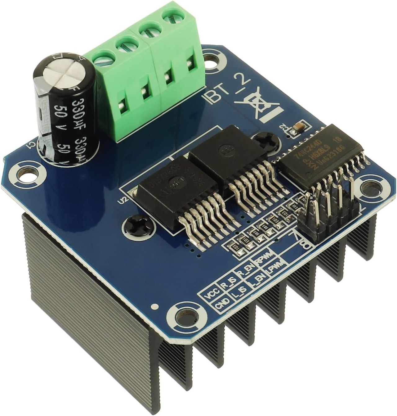
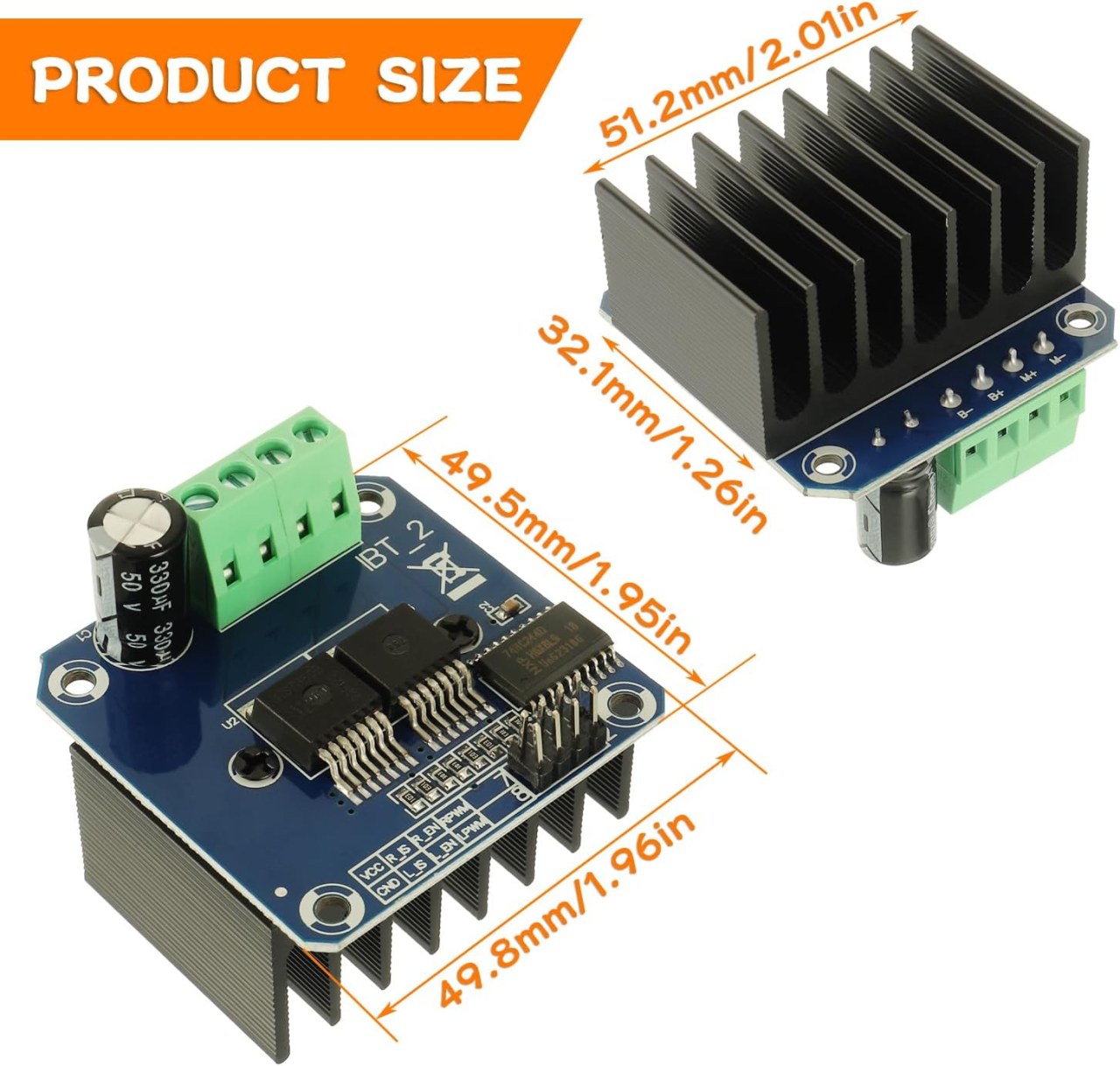
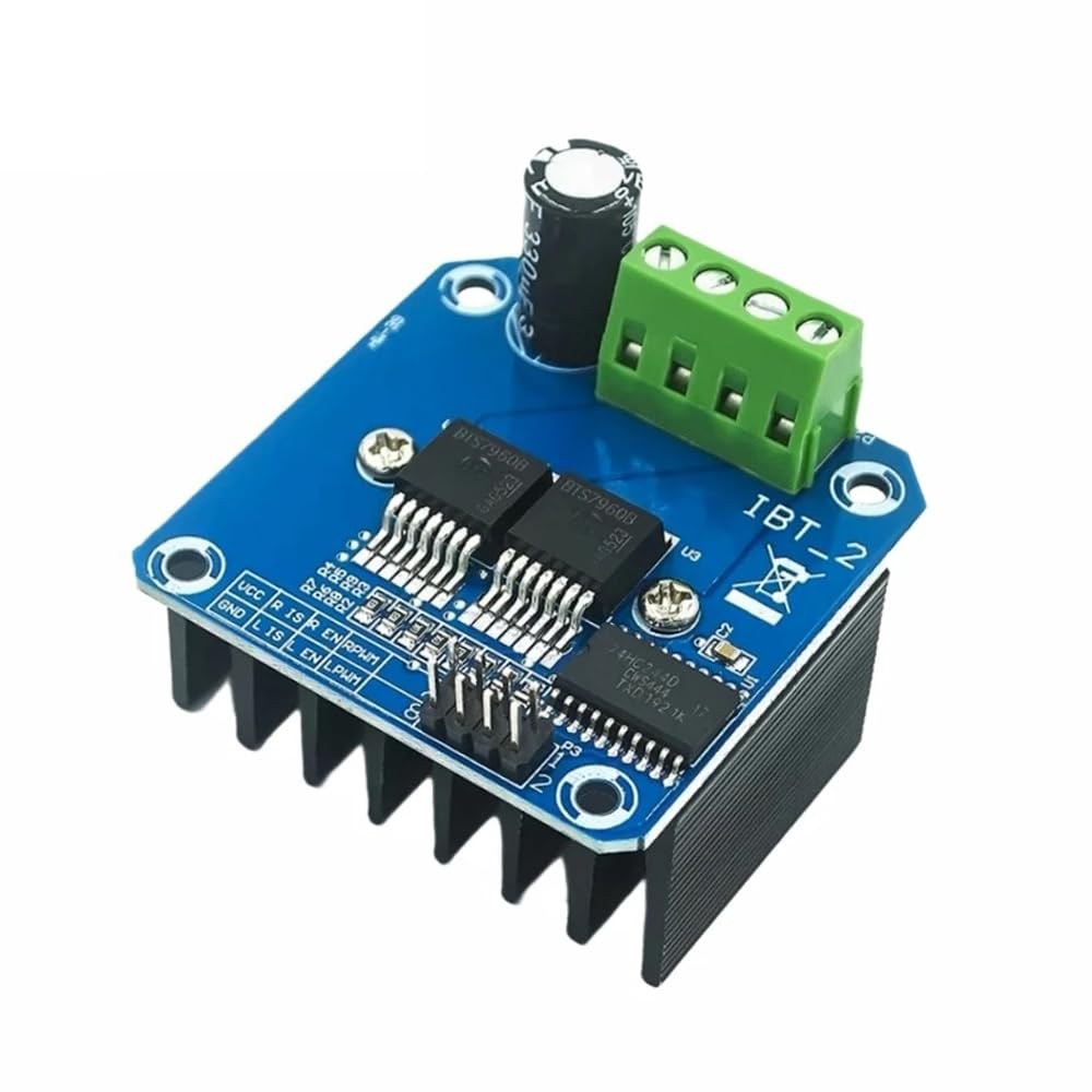
Le BTS7960 est un driver de moteur DC à fort courant capable de gérer jusqu'à 43 Ampères. Il se compose de deux circuits intégrés (CI) qui permettent de contrôler un moteur dans les directions horaire (CW) et antihoraire (CCW). Le driver utilise des signaux PWM pour faire varier la vitesse du moteur, ce qui est essentiel pour les applications nécessitant un contrôle précis.
Un autre aspect important de ce module est ses fonctionnalités de détection de courant et de protection contre la sur-température intégrées. Cela aide à prévenir les dommages au moteur et au pilote durant le fonctionnement. Le module est alimenté par une source externe, et il nécessite également une alimentation séparée de 5V pour ses circuits logiques.
Détails de la fiche technique
| Fabricant | Infineon Technologies |
|---|---|
| Numéro de pièce | BTS7960 |
| Tension logique/IO | 5 V |
| Tension d'alimentation | 6-27 V |
| Courant de sortie (par canal) | 43 A max |
| Courant de crête (par canal) | 60 A |
| Guide sur la fréquence PWM | 25 kHz |
| Seuils logiques d'entrée | 0,8 V (haut), 0,3 V (bas) |
| Chute de tension / RDS(on)/ saturation | 16 mΩ |
| Limites thermiques | 125 °C maximum |
| Colis | PTO-263-7 |
| Notes / variantes | Configuration en pont H double |
- Assurez un bon refroidissement pour les applications à fort courant.
- Utilisez le calibre de fil approprié pour supporter le courant maximum.
- Maintenez la fréquence PWM dans les limites spécifiées pour un rendement optimal.
- Implémentez des condensateurs de découplage près des broches d'alimentation pour stabiliser la tension.
- Surveillez la température pendant le fonctionnement pour éviter la surchauffe.
Instructions de câblage

Pour câbler le module de conducteur de moteur BTS7960 à votre Arduino, vous devrez connecter correctement les terminaux d'alimentation, de masse, de contrôle et de moteur. Commencez par connecter l'alimentation au module.B+etB-terminaux, en s'assurant que la polarité est correcte. LeB+le terminal est l'endroit où se connecte l'alimentation positive, tandis queB-se connecte à la terre.
Ensuite, connectez le moteur à leM+etM-terminaux sur le module. Ceux-ci contrôleront la direction du moteur. Pour les broches de contrôle, connectez les broches de l'Arduino au module comme suit :RPWMà épingler 3,R_ENà la broche 4,R_ISà la broche 5,LPWMà la broche 6,L_ENpour épingler 7, etL_ISau pin 8. Assurez-vous de connecter la masse de l'Arduino à la masse du module également.
Installer la bibliothèque requise
Pour installer lerobojax_BTS7960_motor_driver_librarydans l'IDE Arduino, téléchargez d'abord le fichier ZIP de la bibliothèque à partir du lien fourni. Une fois le fichier enregistré, ouvrez votre IDE Arduino et accédez àEsquisse > Inclure une bibliothèque > Ajouter une bibliothèque .ZIP...Dans la boîte de dialogue de sélection de fichiers, parcourez le fichier ZIP téléchargé, sélectionnez-le et cliquez sur "Ouvrir". L'IDE installera alors la bibliothèque. Vous pouvez confirmer une installation réussie en vérifiant leFichier > Exemplesmenu, où une nouvelle catégorie nommée "Bibliothèque de pilote de moteur Robojax BTS7960" devrait apparaître. Vous pouvez maintenant inclure l'en-tête de la bibliothèque dans votre code avec#include <RobojaxBTS7960.h>.
Exemples de code et guide étape par étape
Le code Arduino pour contrôler le driver de moteur BTS7960 commence par définir les broches nécessaires. Par exemple, la broche pour le signal PWM droit est définie commeRPWMet connecté à la broche 3. De plus, la broche d'activation pour le côté droit est définie commeR_ENet défini sur la broche 4.
#define RPWM 3 // define pin 3 for RPWM pin (output)
#define R_EN 4 // define pin 4 for R_EN pin (input)
Cette configuration permet de contrôler le moteur de manière précise. Dans lesetup()fonction, le moteur est initialisé avecmotor.begin(), qui prépare le conducteur à l'opération.
void setup() {
  Serial.begin(9600);// setup Serial Monitor to display information
  motor.begin(); // Initialize motor
}
Dans leloop()fonction, la direction et la vitesse du moteur sont contrôlées à l'aide de lamotor.rotate(speed, direction)méthode. Par exemple, pour faire tourner le moteur à pleine vitesse dans le sens des aiguilles d'une montre, vous utiliseriezmotor.rotate(100, CW);.
void loop() {
    motor.rotate(100,CW); // run motor with 100% speed in CW direction
    delay(5000); // run for 5 seconds
}
Pour des exemples et des variations plus détaillés, assurez-vous de consulter le code complet chargé en dessous de l'article.
Démonstration / À quoi s'attendre
Lorsque tout est câblé et programmé correctement, vous devriez vous attendre à ce que le moteur tourne dans les deux directions en fonction du code. Au départ, le moteur fonctionnera à pleine vitesse pendant cinq secondes, s'arrêtera pendant trois secondes, puis tournera dans la direction opposée pendant la même durée. Ce cycle se répétera, vous permettant de voir la réactivité du moteur aux signaux PWM.
Les pièges courants incluent une polarité inversée lors de la connexion du moteur ou de l'alimentation, ce qui peut endommager les composants. De plus, assurez-vous que les broches PWM sont correctement assignées dans le code (dans la vidéo à 12:34).
Horodatages vidéo
- 00:00 Début
- 00:48 Matériel expliqué
- 04:06 Fiche technique consultée
- 07:07 Explication du câblage
- 09:00 Code expliqué
- 14:33 Démonstration
- 16:47 Test de courant maximum
- 19:25 Image thermique
- 19:27 Test de code différent
Images
/*
* This is the Arduino code for the BTS7960 DC motor driver.
Using this code, you can control a motor to rotate in both directions: clockwise (CW)
and counter-clockwise (CCW).
Watch the video instructions: https://youtu.be/PUL5DZ9TA2o
📚⬇️ Download and resource page for this video https://robojax.com/RJT169
📚⬇️ Download and resource page https://robojax.com/RJT170

// Written by Ahmad Shamshiri for Robojax.com on
// June 22, 2019 at 14:08 in Ajax, Ontario, Canada.
Get this code and other Arduino codes from Robojax.com.


* BTS7960B
 * Code is available at http://robojax.com/learn/arduino

 * This code is "AS IS" without warranty or liability. Free to be used as long as you keep this note intact.
 * This code has been downloaded from Robojax.com
    This program is free software: you can redistribute it and/or modify
    it under the terms of the GNU General Public License as published by
    the Free Software Foundation, either version 3 of the License, or
    (at your option) any later version.

    This program is distributed in the hope that it will be useful,
    but WITHOUT ANY WARRANTY; without even the implied warranty of
    MERCHANTABILITY or FITNESS FOR A PARTICULAR PURPOSE.  See the
    GNU General Public License for more details.

    You should have received a copy of the GNU General Public License
    along with this program.  If not, see <https://www.gnu.org/licenses/>.

*/

//
#define RPWM 3 // define pin 3 for RPWM pin (output)
#define R_EN 4 // define pin 2 for R_EN pin (input)
#define R_IS 5 // define pin 5 for R_IS pin (output)

#define LPWM 6 // define pin 6 for LPWM pin (output)
#define L_EN 7 // define pin 7 for L_EN pin (input)
#define L_IS 8 // define pin 8 for L_IS pin (output)
#define CW 1 //do not change
#define CCW 0 //do not change
#define debug 1 //change to 0 to hide serial monitor debugging information or set to 1 to view

#include <RobojaxBTS7960.h>
RobojaxBTS7960 motor(R_EN,RPWM,R_IS, L_EN,LPWM,L_IS,debug);

void setup() {
  // BTS7960 Motor Control Code by Robojax.com 20190622
  Serial.begin(9600);// setup Serial Monitor to display information

   motor.begin();
   //watch video for details: https://youtu.be/PUL5DZ9TA2o

    // BTS7960 Motor Control Code by Robojax.com 20190622
}

void loop() {
   // BTS7960 Motor Control Code by Robojax.com 20190622
      //watch video for details: https://youtu.be/PUL5DZ9TA2o
    motor.rotate(100,CW);// run motor with 100% speed in CW direction
    delay(5000);//run for 5 seconds
    motor.stop();// stop the motor
    delay(3000);// stop for 3 seconds
    motor.rotate(100,CCW);// run motor at 100% speed in CCW direction
    delay(5000);// run for 5 seconds
    motor.stop();// stop the motor
    delay(3000);  // stop for 3 seconds
	// slowly speed up the motor from 0 to 100% speed
    for(int i=0; i<=100; i++){
        motor.rotate(i,CCW);
        delay(50);
    }

   // slow down the motor from 100% to 0 with
    for(int i=100; i>0; i--){
        motor.rotate(i,CCW);
        delay(50);
    }

   //watch video for details: https://youtu.be/PUL5DZ9TA2o
    motor.stop();// stop motor
    delay(3000); // stop for 3 seconds
 // BTS7960 Motor Control Code by Robojax.com 20190622
}// loop ends++
/*
* This is the Arduino code for the BTS7960 DC motor driver.
Using this code, you can control more than one motor to rotate in both directions: clockwise (CW)
and counter-clockwise (CCW).
📚⬇️ Download and resource page for this video https://robojax.com/RJT169
📚⬇️ Download and resource page https://robojax.com/RJT170
Written by Ahmad Shamshiri for Robojax.com on
July 16, 2020 in Ajax, Ontario, Canada.
Watch video instructions for this code: https://youtu.be/PUL5DZ9TA2o
BTS7960B
If you found this tutorial helpful, please support me so I can continue creating
content like this. You can support me on Patreon: http://robojax.com/L/?id=63
or make a donation using PayPal: http://robojax.com/L/?id=64
* This code has been downloaded from Robojax.com
This program is free software: you can redistribute it and/or modify
it under the terms of the GNU General Public License as published by
the Free Software Foundation, either version 3 of the License, or
(at your option) any later version.
This program is distributed in the hope that it will be useful,
but WITHOUT ANY WARRANTY; without even the implied warranty of
MERCHANTABILITY or FITNESS FOR A PARTICULAR PURPOSE. See the
GNU General Public License for more details.
You should have received a copy of the GNU General Public License
along with this program. If not, see <https://www.gnu.org/licenses/>.
*/
// pins for motor 1
#define RPWM_1 3 // define pin 3 for RPWM pin (output)
#define R_EN_1 4 // define pin 2 for R_EN pin (input)
#define R_IS_1 5 // define pin 5 for R_IS pin (output)
#define LPWM_1 6 // define pin 6 for LPWM pin (output)
#define L_EN_1 7 // define pin 7 for L_EN pin (input)
#define L_IS_1 8 // define pin 8 for L_IS pin (output)
// motor 1 pins end here
// pins for motor 2
#define RPWM_2 9 // define pin 9 for RPWM pin (output)
#define R_EN_2 10 // define pin 10 for R_EN pin (input)
#define R_IS_2 12 // define pin 12 for R_IS pin (output)
#define LPWM_2 11 // define pin 11 for LPWM pin (output)
#define L_EN_2 A0 // define pin 7 for L_EN pin (input)
#define L_IS_2 A1 // define pin 8 for L_IS pin (output)
// motor 2 pins end here
#define CW 1 //
#define CCW 0 //
#define debug 1 //
#include <RobojaxBTS7960.h>
RobojaxBTS7960 motor1(R_EN_1,RPWM_1,R_IS_1, L_EN_1,LPWM_1,L_IS_1,debug);//define motor 1 object
RobojaxBTS7960 motor2(R_EN_2,RPWM_2,R_IS_2, L_EN_2,LPWM_2,L_IS_2,debug);//define motor 2 object and the same way for other motors
void setup() {
// BTS7960 Motor Control Code by Robojax.com 20190622
Serial.begin(9600);// setup Serial Monitor to display information
motor1.begin();
motor2.begin();
// BTS7960 Motor Control Code by Robojax.com 20190622
}
void loop() {
// BTS7960 Motor Control Code by Robojax.com 20190622
motor1.rotate(100,CW);// run motor 1 with 100% speed in CW direction
delay(5000);//run for 5 seconds
motor1.stop();// stop the motor 1
delay(3000);// stop for 3 seconds
motor1.rotate(100,CCW);// run motor 1 at 100% speed in CCW direction
delay(5000);// run for 5 seconds
motor1.stop();// stop the motor 1
delay(3000); // stop for 3 seconds
motor2.rotate(100,CW);// run motor 2 with 100% speed in CW direction
delay(5000);//run for 5 seconds
motor2.stop();// stop the motor 2
delay(3000);// stop for 3 seconds
motor2.rotate(100,CCW);// run motor 2 at 100% speed in CCW direction
delay(5000);// run for 5 seconds
motor2.stop();// stop the motor 2
delay(3000); // stop for 3 seconds
// slowly speed up the motor 1 from 0 to 100% speed
for(int i=0; i<=100; i++){
motor1.rotate(i,CCW);
delay(50);
}
// slow down the motor 2 from 100% to 0
for(int i=100; i>0; i--){
motor2.rotate(i,CCW);
delay(50);
}
motor2.stop();// stop motor 2
delay(3000); // stop for 3 seconds
// BTS7960 more than 1 Motor Control Code by Robojax.com 20190622
}// loop endsRessources et références
-
Externe
-
ExterneAchetez le BTS7960 sur Amazonamzn.to
-
Externe
-
ExterneBTS7960 Amazon Japonamzn.to
-
ExterneBTS7960 sur Amazon Espagneamzn.to
-
ExterneBTS7960 sur Amazon Franceamzn.to
-
ExterneBTS7960 sur Amazon Italieamzn.to
-
ExterneBTS7960, Amazon Allemagneamzn.to
Fichiers📁
Bibliothèques Arduino (zip)
-
robojax_BTS7960_bibliothèque_de_conducteur_moteur
robojax_BTS7960_motor_driver_library.zip0.10 MB
Fiche technique (pdf)
-
BTS7960_fiche technique
BTS7960_datasheet.pdf0.45 MB
Fichier Fritzing
-
BTS7960_driver
BTS7960_driver.fzpz0.01 MB