DS3231 Real-Time Alarm Clock Module: Turn Buzzer and LED On
The DS3231 is a highly accurate, low-cost Real-Time Clock (RTC) module that maintains the current time, date, and calendar even when your main power source is disconnected, thanks to its backup battery. This tutorial demonstrates how to interface the DS3231 with an Arduino to display time in various formats on the Serial Monitor. More importantly, it shows you how to configure two independent alarms to trigger external actions, such as turning on a buzzer and an LED. This capability transforms a simple clock into a powerful time-based controller for a wide range of applications.
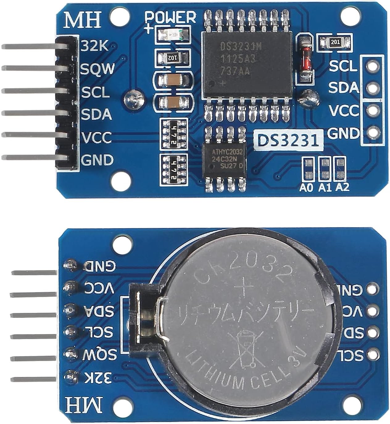
This project is perfect for building practical, time-aware devices. Here are a few ideas to inspire you:
- Automated Schedulers: Create a device that turns on a coffee maker or water pump at a specific time each day.
- Security Timers: Build a system that locks or unlocks a door, or activates a security light, based on a set schedule.
- Reminder Systems: Develop a personal reminder that sounds a buzzer for medication schedules or hourly breaks.
- Data Loggers: Use the RTC to timestamp sensor readings in an environmental monitoring project.
- School Bell System: Simulate a school bell that rings at different times for class changes.
-
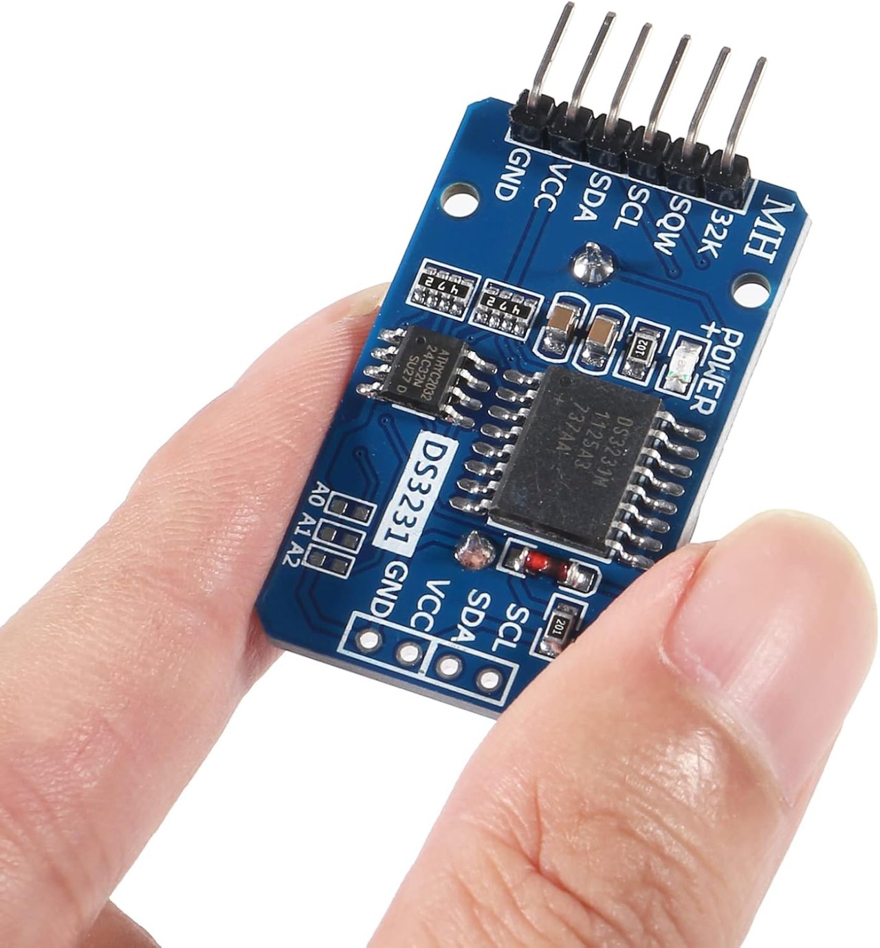
DS3231-rtc-module-0-scale-in-hand
Hardware Overview
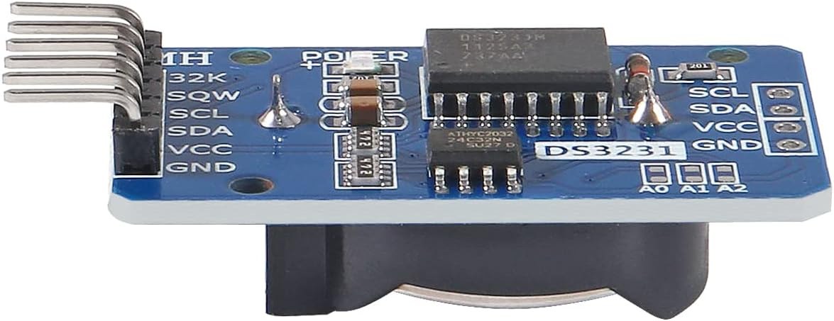
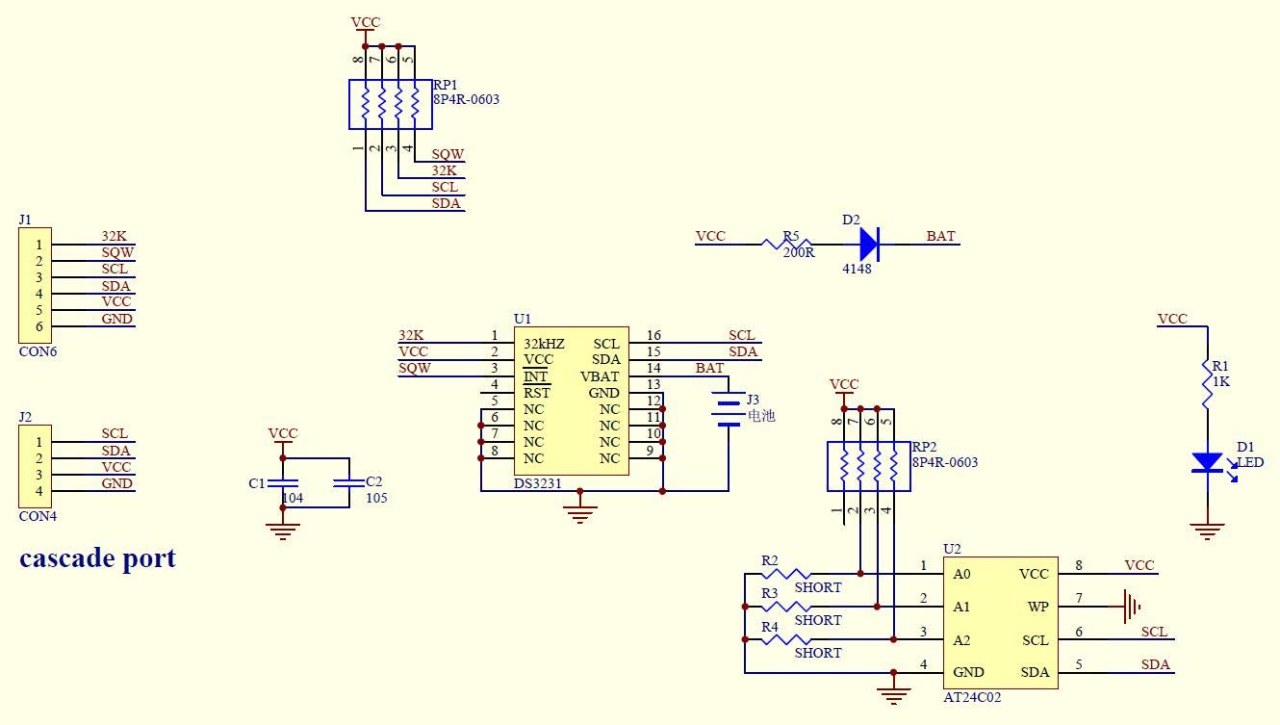
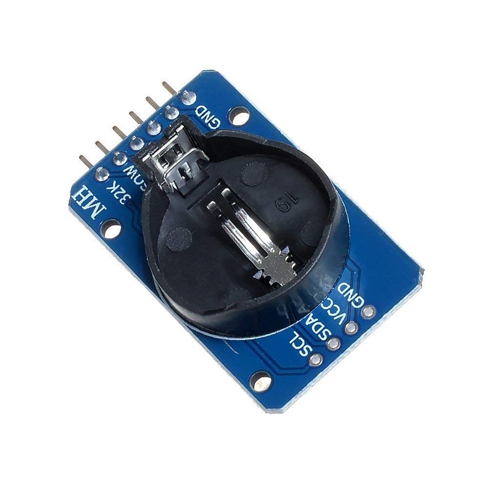
The DS3231 module is a complete, self-contained timekeeping solution. The heart of the module is the DS3231 chip from Maxim Integrated, which is famous for its exceptional accuracy (±2 ppm), making it much more precise than typical RTCs. It communicates with the Arduino via the I2C protocol, requiring only two pins for data transfer (SDA and SCL). The module features a socket for a CR2032 lithium battery. When external power is removed, the module switches to battery power to keep the clock running, ensuring your time and alarm settings are never lost.
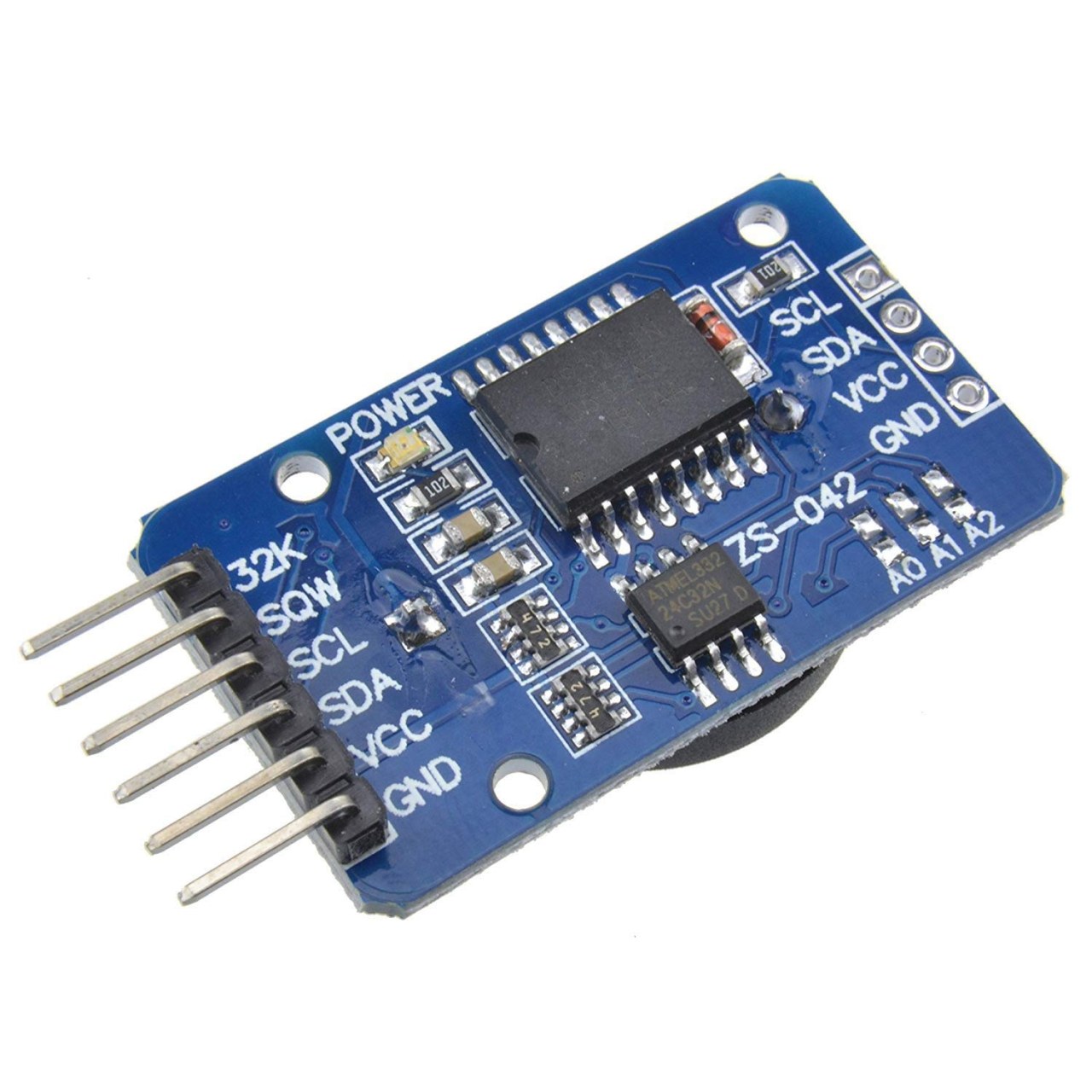
As explained in the video (in video at 00:53), the module has several key pins:
- VCC: Connects to the 5V pin on the Arduino.
- GND: Connects to the ground (GND) pin on the Arduino.
- SDA: The I2C data line.
- SCL: The I2C clock line.
- SQW: A square wave output pin. The frequency (1Hz, 1.024kHz, 4.096kHz, or 8.192kHz) can be configured in software (in video at 01:56).
- 32K: An output for the chip's internal 32.768kHz oscillator (in video at 02:08).
Required Components
To build this project, you will need the following components:
- 1x Arduino Board (Uno, Nano, Mega, etc.)
- 1x DS3231 Real-Time Clock Module
- 1x CR2032 Battery (for the RTC module)
- 1x Buzzer (or LED)
- 1x LED (or second buzzer)
- 2x Resistors (e.g., 220Ω for the LEDs)
- Jumper Wires
- Breadboard (optional, for easy prototyping)
Wiring Guide
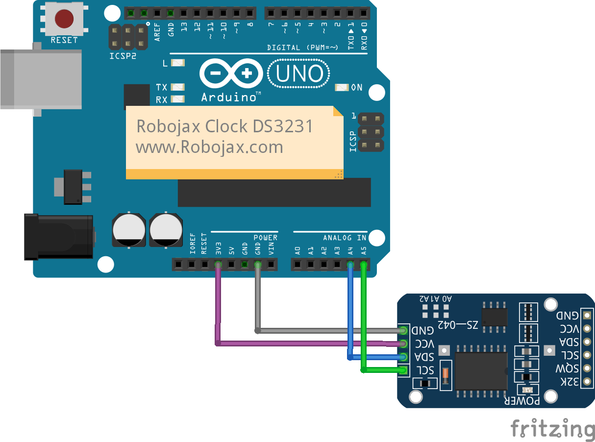
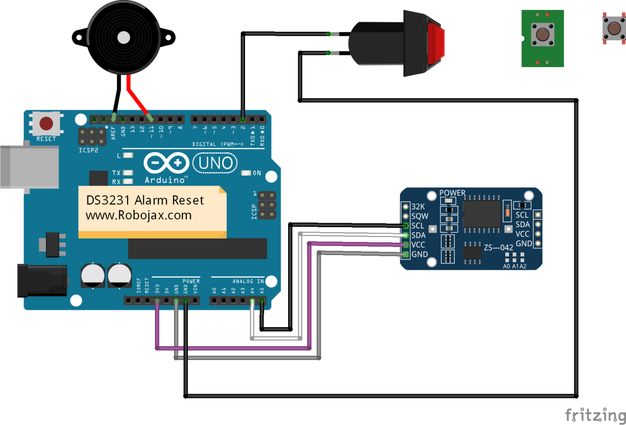
The wiring for this project is straightforward, as the DS3231 uses the I2C protocol. Connect the components as follows:
- VCC: DS3231 VCC pin to Arduino 5V.
- GND: DS3231 GND pin to Arduino GND.
- SDA: DS3231 SDA pin to Arduino A4 (on Uno/Nano) or pin 20 (on Mega) (in video at 04:49).
- SCL: DS3231 SCL pin to Arduino A5 (on Uno/Nano) or pin 21 (on Mega) (in video at 04:49).
- Alarm 1 Output: Connect the buzzer's positive lead to Arduino pin 2 and the negative lead to GND.
- Alarm 2 Output: Connect the LED's anode (long leg) through a 220Ω resistor to Arduino pin 3, and the cathode (short leg) to GND.
Code Explanation
This project uses the Arduino-DS3231 library by Korneliusz Jarzebski, which simplifies communication with the RTC. You will need to download and install this library via the Arduino IDE's Library Manager or by adding the .zip file (in video at 05:51). The code provided is designed to set two alarms and control external devices when they trigger. Let's break down the user-configurable parts.
#define  alarm1Pin 2
#define  alarm2Pin 3
These two lines define the Arduino pins that will be used to trigger your external devices (buzzer, LED, relay, etc.). You can change the pin numbers (2 and 3) to any other digital pins on your Arduino, depending on your wiring (in video at 18:03).
// Manual (Year, Month, Day, Hour, Minute, Second)
clock.setDateTime(2014, 4, 25, 0, 0, 0);
This line sets the initial date and time on the DS3231. The code sets a specific time (2014, April 25th, at 00:00:00) for demonstration purposes, so you don't have to wait long for the alarms to trigger. In a real-world application, you would set this to the current date and time. Once set, the module's battery will keep the time running even if the Arduino is unplugged.
// Set Alarm1 - Every 20s in each minute
// setAlarm1(Date or Day, Hour, Minute, Second, Mode, Armed = true)
clock.setAlarm1(0, 0, 0, 20, DS3231_MATCH_S);

// Set Alarm2 - Every 01m in each hour
// setAlarm2(Date or Day, Hour, Minute, Mode, Armed = true)
clock.setAlarm2(0, 0, 1,     DS3231_MATCH_M);
These are the core alarm configuration functions. They are set to trigger Alarm 1 every time the seconds reach 20 (e.g., at 10:05:20, 10:06:20), and Alarm 2 every time the minutes reach 1 (e.g., at 10:01, 11:01). The library provides several other matching modes (commented out in the code) that allow for more complex schedules, such as matching a specific day of the week, a date in the month, or a specific hour, minute, and second (in video at 10:53).
The behavior when each alarm triggers is handled in the loop() function. When clock.isAlarm1() returns true, the code turns alarm1Pin HIGH for 3 seconds. For alarm2Pin, it creates a beeping pattern by turning the pin HIGH and LOW several times. You can modify this section to control any device, such as a relay or a motor, for any duration you require (in video at 18:34).
Live Project Demonstration
Once the code is uploaded, the Arduino will begin running. The Serial Monitor will display the current date and time every second. The project demonstrates two key behaviors:
- Simple Clock: The first demonstration shows how to read and display the time in various formats, including 24-hour, 12-hour, and long-form date strings (in video at 13:48).
- Alarm Triggering: The second demonstration shows the alarms in action. When Alarm 1 triggers, you will see "ALARM 1 TRIGGERED!" on the Serial Monitor, and the buzzer will sound for 3 seconds. When Alarm 2 triggers, you will see "ALARM 2 TRIGGERED!", and the LED will blink several times (in video at 17:28).
Chapters
- [00:00] Introduction
- [00:48] Hardware Explained
- [04:23] Wiring Explained
- [05:45] Code Explained: Simple Clock
- [09:42] Code Explained: Alarm Example
- [13:46] Arduino Running Code Demonstration
- [15:41] Arduino Running Alarm Code Demonstration
- [17:28] Alarm Buzzer Demonstration
Aworan
/*
 *
  DS3231: Real-Time Clock. Alarm simple
  Alarm Pins have been defined to turn Buzzer ON
  Updated by Ahmad Shamshiri on Jun 11, 2019 at 22:15
  in Ajax, Ontario -- Robojax.com
  You can support me on Patreon http://bit.ly/2ZnITLz

  Watch video instruction for this code: https://youtu.be/7hBtXdoaAOY


  Read more: www.jarzebski.pl/arduino/komponenty/zegar-czasu-rzeczywistego-rtc-DS3231.html
  GIT: https://github.com/jarzebski/Arduino-DS3231
  Web: http://www.jarzebski.pl
  (c) 2014 by Korneliusz Jarzebski
*/

#include <Wire.h>
#include <DS3231.h>

DS3231 clock;
RTCDateTime dt;

#define  alarm1Pin 2
#define  alarm2Pin 3
void setup()
{
  Serial.begin(9600);
  pinMode(alarm1Pin,OUTPUT);//
  pinMode(alarm2Pin,OUTPUT);

  // Initialize DS3231
  Serial.println("Initialize DS3231");;
  clock.begin();

  // Disarm alarms and clear alarms for this example, because alarms are battery backed.
  // Under normal conditions, the settings should be reset after power and microcontroller restart.
  clock.armAlarm1(false);
  clock.armAlarm2(false);
  clock.clearAlarm1();
  clock.clearAlarm2();

  // Manual (Year, Month, Day, Hour, Minute, Second)
  clock.setDateTime(2014, 4, 25, 0, 0, 0);

  // Set Alarm - Every second.
  // DS3231_EVERY_SECOND is available only on Alarm1.
  // setAlarm1(Date or Day, Hour, Minute, Second, Mode, Armed = true)
  // clock.setAlarm1(0, 0, 0, 0, DS3231_EVERY_SECOND);

  // Set Alarm - Every full minute.
  // DS3231_EVERY_MINUTE is available only on Alarm2.
  // setAlarm2(Date or Day, Hour, Minute, Second, Mode, Armed = true)
  // clock.setAlarm2(0, 0, 0, 0, DS3231_EVERY_MINUTE);

  // Set Alarm1 - Every 20s in each minute
  // setAlarm1(Date or Day, Hour, Minute, Second, Mode, Armed = true)
  clock.setAlarm1(0, 0, 0, 20, DS3231_MATCH_S);

  // Set Alarm2 - Every 01m in each hour
  // setAlarm2(Date or Day, Hour, Minute, Mode, Armed = true)
  clock.setAlarm2(0, 0, 1,     DS3231_MATCH_M);

  // Set Alarm - Every 01m:25s in each hour
  // setAlarm1(Date or Day, Hour, Minute, Second, Mode, Armed = true)
  // clock.setAlarm1(0, 0, 1, 25, DS3231_MATCH_M_S);

  // Set Alarm - Every 01h:10m:30s in each day
  // setAlarm1(Date or Day, Hour, Minute, Second, Mode, Armed = true)
  // clock.setAlarm1(0, 1, 10, 30, DS3231_MATCH_H_M_S);

  // Set Alarm - 07h:00m:00s in 25th day in month
  // setAlarm1(Date or Day, Hour, Minute, Second, Mode, Armed = true)
  // clock.setAlarm1(25, 7, 0, 0, DS3231_MATCH_DT_H_M_S);

  // Set Alarm - 10h:45m:30s in every Friday (1 - Mon, 7 - Sun)
  // setAlarm1(Date or Day, Hour, Minute, Second, Mode, Armed = true)
  // clock.setAlarm1(5, 10, 40, 30, DS3231_MATCH_DY_H_M_S);

  // Check alarm settings
  checkAlarms();
}

void checkAlarms()
{
  RTCAlarmTime a1;
  RTCAlarmTime a2;

  if (clock.isArmed1())
  {
    a1 = clock.getAlarm1();

    Serial.print("Alarm1 is triggered ");
    switch (clock.getAlarmType1())
    {
      case DS3231_EVERY_SECOND:
        Serial.println("every second");
        break;
      case DS3231_MATCH_S:
        Serial.print("when seconds match: ");
        Serial.println(clock.dateFormat("__ __:__:s", a1));
        break;
      case DS3231_MATCH_M_S:
        Serial.print("when minutes and seconds match: ");
        Serial.println(clock.dateFormat("__ __:i:s", a1));
        break;
      case DS3231_MATCH_H_M_S:
        Serial.print("when hours, minutes and seconds match: ");
        Serial.println(clock.dateFormat("__ H:i:s", a1));
        break;
      case DS3231_MATCH_DT_H_M_S:
        Serial.print("when date, hours, minutes and seconds match: ");
        Serial.println(clock.dateFormat("d H:i:s", a1));
        break;
      case DS3231_MATCH_DY_H_M_S:
        Serial.print("when day of week, hours, minutes and seconds match: ");
        Serial.println(clock.dateFormat("l H:i:s", a1));
        break;
      default:
        Serial.println("UNKNOWN RULE");
        break;
    }
  } else
  {
    Serial.println("Alarm1 is disarmed.");
  }

  if (clock.isArmed2())
  {
    a2 = clock.getAlarm2();

    Serial.print("Alarm2 is triggered ");
    switch (clock.getAlarmType2())
    {
      case DS3231_EVERY_MINUTE:
        Serial.println("every minute");
        break;
      case DS3231_MATCH_M:
        Serial.print("when minutes match: ");
        Serial.println(clock.dateFormat("__ __:i:s", a2));
        break;
      case DS3231_MATCH_H_M:
        Serial.print("when hours and minutes match:");
        Serial.println(clock.dateFormat("__ H:i:s", a2));
        break;
      case DS3231_MATCH_DT_H_M:
        Serial.print("when date, hours and minutes match: ");
        Serial.println(clock.dateFormat("d H:i:s", a2));
        break;
      case DS3231_MATCH_DY_H_M:
        Serial.println("when day of week, hours and minutes match: ");
        Serial.print(clock.dateFormat("l H:i:s", a2));
        break;
      default:
        Serial.println("UNKNOWN RULE");
        break;
    }
  } else
  {
    Serial.println("Alarm2 is disarmed.");
  }
}

void loop()
{
  dt = clock.getDateTime();

  Serial.println(clock.dateFormat("d-m-Y H:i:s - l", dt));

  // Call isAlarm1(false) if you want to clear alarm1 flag manually by calling clearAlarm1();
  if (clock.isAlarm1())
  {
    Serial.println("ALARM 1 TRIGGERED!");
    digitalWrite(alarm1Pin,HIGH);
    delay(3000);
    digitalWrite(alarm1Pin,LOW);
  }

  // Call isAlarm2(false) if you want to clear alarm2 flag manually by calling clearAlarm2();
  if (clock.isAlarm2())
  {
    Serial.println("ALARM 2 TRIGGERED!");
    digitalWrite(alarm2Pin,HIGH);
    delay(300);
    digitalWrite(alarm2Pin,LOW);
    delay(300);
    digitalWrite(alarm2Pin,HIGH);
    delay(300);
    digitalWrite(alarm2Pin,LOW);
    delay(300);
    digitalWrite(alarm2Pin,HIGH);
    delay(300);
    digitalWrite(alarm2Pin,LOW);
    delay(300);
    digitalWrite(alarm2Pin,HIGH);
    delay(300);
    digitalWrite(alarm2Pin,LOW);
  }

  delay(1000);
}
Orisun & itọkasi
Ko si awọn orisun sibẹsibẹ.
Fáìlìs📁
Ko si awọn faili ti o wa.