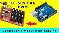
Control XY-1250 10–50A/60A 3000W PWM Motor Speed Controller Using Arduino
In this tutorial, we'll show you how to take a common XY-1250 PWM motor speed controller (rated for 10–50A/60A at up to 3000W) and modify it so you can control its speed with an Arduino instead of its built-in knob. This is a popular request from hobbyists who want to integrate a high-power motor controller into their own projects—like building a custom electric longboard, a CNC spindle speed control, a robotic drive system, or an automated fan system. By replacing the manual potentiometer with a digital signal, you gain precise, programmable control over your motor's speed, which opens up a world of possibilities for automation and remote operation.
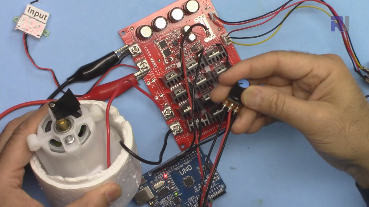
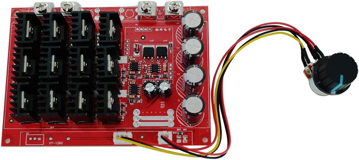
Here are some practical projects you can build with this setup:
- Building a custom electric longboard or go-kart with programmable speed ramping.
- Creating a CNC machine spindle speed controller that can be adjusted via G-code.
- Building an automated greenhouse fan that adjusts speed based on temperature sensors.
- Making a remote-controlled robot with high-torque motors.
- Developing a smart conveyor belt system for a workshop or small factory.
Hardware Components
- XY-1250 PWM motor speed controller module (10–50A/60A, 3000W)
- Arduino Uno (or any compatible board)
- DC motor (for testing)
- DC power supply (12V–36V recommended)
- Potentiometer (10kΩ) — for manual control option
- Jumper wires
- Soldering iron and wire (for modifying the PCB)
How the XY-1250 Works
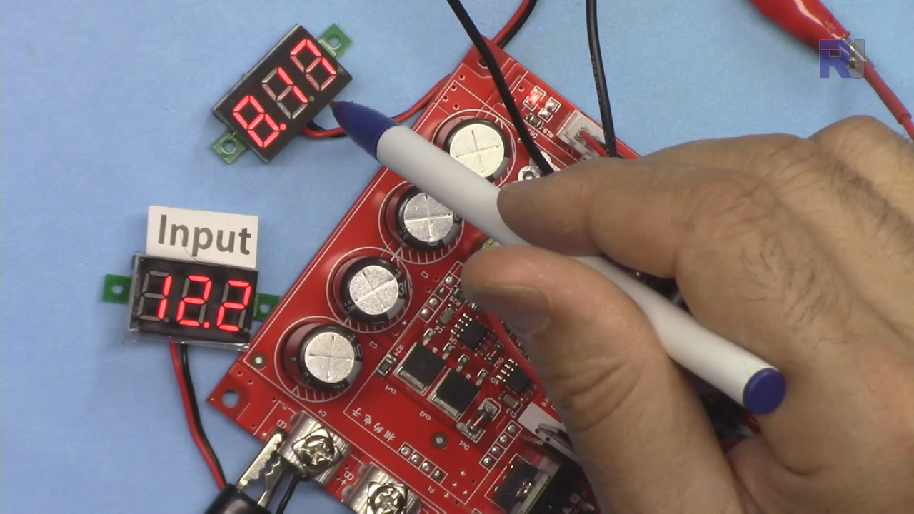
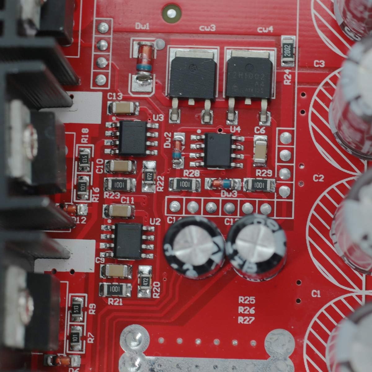
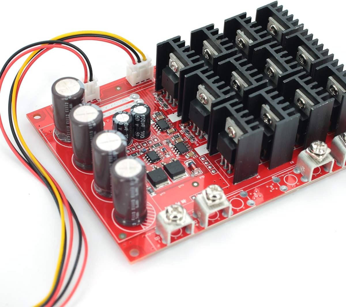
The XY-1250 uses a 555 timer IC (labeled as "U3" on the board) to generate a PWM signal. This signal controls the gate of four MOSFETs that switch the high-power motor circuit. The duty cycle—which determines the motor speed—is normally set by the onboard potentiometer connected to pin 3 of the 555 timer. To control this with an Arduino, we need to disconnect the 555's output from the MOSFET gates and feed in our own PWM signal instead.
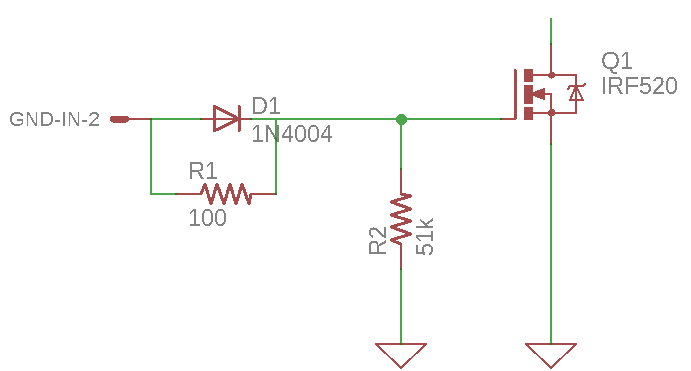
This modification is necessary because the Arduino cannot directly drive the high-current MOSFET gates. By cutting the PCB traces between the 555 timer and the MOSFETs, we can safely inject our own low-voltage PWM signal from the Arduino, giving us full digital control over the motor speed. (in video at 01:42)
Modifying the XY-1250 Board
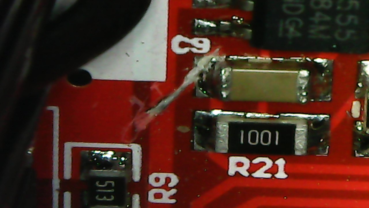
Before we can connect the Arduino, we need to make two cuts on the PCB to isolate the 555 timer's output from the MOSFET gates. Here's how to do it:
- Locate the 555 timer chip (U3) on the board. It has a small dot or line indicating pin 1.
- Identify the PCB traces coming from pin 3 (the output) that lead to the diodes connected to the MOSFET gates.
- Using a sharp knife or a rotary tool with a cutting disc, carefully cut these traces in two places—one for each output path.
- After cutting, use a continuity tester to verify the cut is complete. You should hear no beep between the 555's pin 3 and the MOSFET gate area.
This modification is critical—it prevents the 555 timer's signal from interfering with our Arduino's PWM signal. (in video at 07:02)
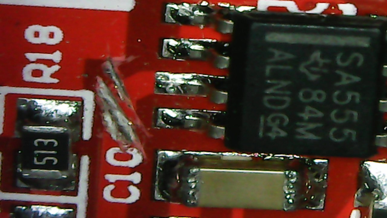
Wiring Guide
The wiring for this project involves connecting the Arduino to the modified XY-1250 board. Here's the connection diagram:
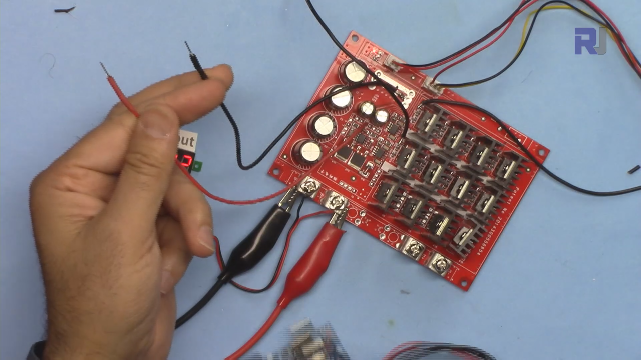
- Power for Arduino: The XY-1250 has a voltage regulator that outputs approximately 8.5V. Connect this output (the red wire between the two capacitors) to the Arduino's VIN pin. This powers the Arduino directly from the motor's power supply. Important: Do not connect this to the 5V pin—it will burn the Arduino.
- Ground connection: Connect the ground from the XY-1250 to any GND pin on the Arduino.
- PWM signals: Connect Arduino pin 5 to the first cut trace (where the 555's output was), and Arduino pin 6 to the second cut trace.
- Potentiometer (optional): If you want manual control, connect a 10kΩ potentiometer to the Arduino's A0 pin, with the other two pins to 5V and GND.
- Motor: Connect your DC motor to the output terminals of the XY-1250 module.
Once wired, the Arduino will be powered by the same supply as the motor, and it will send synchronized PWM signals to both MOSFET gate circuits. (in video at 10:25)
Code Explanation
The Arduino code is straightforward and focuses on generating the PWM signals. Here are the key user-configurable parts:
#define pwmPin1 5
#define pwmPin2 6
#define controlPin A0
pwmPin1andpwmPin2are the Arduino pins that send the PWM signal to the two MOSFET gate circuits. These are defined as pins 5 and 6, which are both PWM-capable pins on the Arduino Uno.controlPinis the analog pin connected to the potentiometer (A0). If you don't want to use a potentiometer, you can ignore this.
In the loop() function, the code reads the potentiometer value (0–1023), maps it to a PWM value (0–255), and sends it to both PWM pins. The delay(500) sets the refresh rate to twice per second—you can reduce this to delay(100) for smoother response.
The code also includes a custom toPWM() function that converts a percentage value (0–100) to a PWM value (0–255). This is useful if you want to set a specific speed without a potentiometer. For example, calling toPWM(50) would return 127, representing 50% duty cycle. You can use this function in your own code to set the motor speed directly.
Testing and Demonstration
After uploading the code and connecting everything, you can test the setup. If you're using a potentiometer, rotating it will smoothly adjust the motor speed from 0 to 100%. The serial monitor will display both the raw analog value (0–1023) and the mapped PWM value (0–255).
If you want to control the speed programmatically, you can replace the potentiometer reading with a fixed value. For example, setting int pwm = toPWM(20); will run the motor at 20% speed. This is perfect for applications where you want the motor to run at a specific speed without manual adjustment. (in video at 16:42)
Live Project Demonstration
In the video, you can see the modified XY-1250 controller driving a small DC motor. The demonstration shows:
- Controlling the motor speed with a potentiometer connected to the Arduino.
- Setting the motor to a fixed 20% speed using the
toPWM()function. - Increasing the speed to 50% and then 80% to show the full range of control.
The oscilloscope readings confirm that both PWM signals are perfectly synchronized, with no phase difference between the two channels. This ensures the MOSFETs are driven evenly, preventing uneven wear or overheating. (in video at 14:56)
Chapters
- [00:00] Introduction and project overview
- [01:42] How the XY-1250 PWM controller works
- [04:28] Testing the original signal with an oscilloscope
- [07:02] Cutting the PCB traces to isolate the 555 timer
- [10:25] Wiring the Arduino to the modified module
- [12:18] Explaining the Arduino code
- [14:56] Demonstrating motor control with a potentiometer
- [16:42] Controlling speed programmatically with fixed values
- [20:32] Final summary and closing remarks
Beelde
/*
 * Modify XY-1250 12-50V 60A PWM to work with Arduino.
get this code and other resouces http://robojax.com/RTJ162
If you want to control it without a potentiometer, see http://robojax.com/RTJ162
 *
 * Written by Ahmad Shamshiri
 * on Saturday, June 15, 2019 at 16:14
 * in Ajax, Ontario, Canada
 * www.robojax.com
 * Watch the video instruction: https://youtu.be/k13iTmvPtUU
 */
#define pwmPin1 5
#define pwmPin2 6
#define controlPin A0

void setup() {
  pinMode(pwmPin1,OUTPUT);
  pinMode(pwmPin2,OUTPUT);
  Serial.begin(9600);

}

void loop() {
  int potValue = analogRead(controlPin);
  Serial.print(potValue);
  int pwm =map(potValue, 0,1023, 0, 255);

  analogWrite(pwmPin1,pwm);
  analogWrite(pwmPin2,pwm);
  Serial.print(" ");
  Serial.println(pwm);
  delay(500);
}

/*
 * @brief Converts a percentage value from 0 to 100% to 0-255.
 * @param v An integer value representing a percentage from 0-100.
 * @return A value from 0 to 255.
 */
int toPWM(int v){
  return map(v, 0,100,0,255);
}/*
* file: PWM_for_XY1260_module_no_pot
* Modify XY-1250 12-50V 60A PWM to work with Arduino
* This code allows you to control the motor without a potentiometer. See video for demonstration.
* resources page for this project https://robojax.com/RTJ162
Watch the video instruction on youTube: https://youtu.be/ZLZr2AZgmPI
*
* How to use:
* To control speed at 100%
motorControl(100);
delay(3000);//keep it running for 3 seconds
* To control speed at 400%
motorControl(40);
delay(3000);//keep it running for 3 seconds
* To stop motor
motorControl(0); //set zero
delay(3000);//keep it running for 3 seconds
* Written by Ahmad Shamshiri
* on Saturday, January 30, 2021, at 12:49
* in Ajax, Ontario, Canada
* www.Robojax.com
* Watch the video instruction: https://youtu.be/ZLZr2AZgmPI
*/
#define pwmPin1 3
#define pwmPin2 6
bool defaultMotorON = false;// or set to "true" to make the motor start
unsigned int defaultSpeed= 20;//20% set it in % 0=stop, 100=full speed
int toPWM(int);//prototype
void setup() {
pinMode(pwmPin1,OUTPUT);
pinMode(pwmPin2,OUTPUT);
Serial.begin(9600);
Serial.print("Control XY-1260 without pot");
if(defaultMotorON){
analogWrite(pwmPin1,toPWM(defaultSpeed));
analogWrite(pwmPin2,toPWM(defaultSpeed));
}else{
analogWrite(pwmPin1,0);
analogWrite(pwmPin2,0);
}
}
void loop() {
motorControl(100);//set speed to 100%
delay(3000);//keep motor running at 100% for 3 seconds
motorControl(0);//stops motor
delay(4000);//keep motor stopped for 4 seconds
motorControl(45);//set speed to 45%
delay(3000);//keep motor running at 45% for 3 seconds
motorControl(0);//stops motor
delay(4000);//keep motor stopped for 4 seconds
//from 0 to 100% with 50 millisecond delay (increasing speed)
for(int i=0; i<100; i++)
{
motorControl(i);//set speed with value of i from 0 to 100
delay(50);//give motor 50 milliseconds before going to the next value
}//for loop end
motorControl(0);//stops motor
delay(4000);//keep motor stopped for 4 seconds
//from 100% to 10 with 50 millisecond delay (decreasing speed)
for(int i=100; i>0; i--)
{
motorControl(i);//set speed with value of i from 0 to 100
delay(50);//give motor 50 milliseconds before going to the next value
}//for loop end
motorControl(0);//stops motor
delay(4000);//keep motor stopped for 4 seconds
}//loop end
/*
* @brief converts % value from 0 to 100% to 0-255
* @param v is integer value representing % from 0-100
* @return will return value from 0 to 255
*/
int toPWM(int v){
return map(v, 0,100,0,255);
}//
/*
* @brief controls the speed of motor with value from 0 to 100%
* @param speed is integer value representing % from 0-100
* @return none
* written January 30, 2021 by Ahmad Shamshiri
* www.robojax.com
*
*/
void motorControl(int speed)
{
int pwm= map(speed, 0,100,0,255);
analogWrite(pwmPin1,pwm);
analogWrite(pwmPin2,pwm);
}Goedere wat jy dalk nodig het
-
Amazon
-
Amazon60A 3000W PWM module on Amazonamzn.to
-
eBay
-
eBay60A 3000W PWM module on eBayebay.us
-
AliExpress60A 100A Motor Speed Controller on AliExpress-1s.click.aliexpress.com
-
AliExpress60A 100A Motor Speed Controller on AliExpress-2s.click.aliexpress.com
-
AliExpress60A 3000W PWM module on AliExpresss.click.aliexpress.com
-
Banggood60A 100A Motor Speed Controller on Banggoodbanggood.com
Hulpbronne en verwysings
-
Buitenburg
-
BuitenburgDatasheet for NCE7190A MOSFET (8 pieces) (PDF)datasheet.lcsc.com
-
BuitenburgSchottky diode MBR20100CTG datasheet (PDF)onsemi.com
Lêers📁
Geen lêers beskikbaar.