This tutorial is part of: 使用 Arduino 控制继电器
这里是所有与接力赛相关的视频合集。其他视频的链接在本文下方。
TTP224 4通道觸摸感測器,用繼電器控制交流/直流負載
TTP224電容觸摸模組係一個多功能元件,容許用戶透過觸摸輸入嚟控制交流同直流負載(好似燈、風扇、摩打)。喺呢個教學入面,我哋會示範點樣將TTP224連接到Arduino嚟操作一個繼電器,令你可以淨係靠觸摸就開關你嘅燈或者其他設備。完成呢個指南之後,你就會有一個完全正常運作嘅觸摸感應控制系統嚟控制你嘅電器設備。如果想睇視覺化嘅示範,記得睇吓條片(片入面00:00)。
硬件解釋
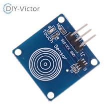
呢個項目用到嘅主要元件包括TTP224電容觸摸模組、一塊Arduino板同一個繼電器模組。TTP224模組透過電容感應嚟偵測觸摸,即係話當手指靠近佢嘅感應墊時,佢可以量度電容嘅變化嚟記錄觸摸。呢個模組有四個輸出,對應四個唔同嘅觸摸輸入,容許你控制多個設備。 繼電器模組扮演一個開關嘅角色,可以安全咁控制高壓交流負載。呢個教學用嘅繼電器係低電平觸發,即係話當繼電器模組輸入端嘅訊號係LOW時,繼電器就會開啟;當訊號係HIGH時,繼電器就會關閉。當繼電器啟動時,佢會將公共端連接到常開端,令電流可以流到連接嘅設備。繼電器由Arduino控制,Arduino讀取TTP224嘅輸出,然後相應咁啟動繼電器。數據手冊詳情
| 製造商 | Vishay |
|---|---|
| 零件編號 | TTP224 |
| 邏輯/IO電壓 | 2.2 – 5.5 V |
| 輸出電流(每通道) | 10 mA(最大) |
| 輸入邏輯閾值 | 0.3 V(低),0.7 V(高) |
| 封裝 | 16針DIP |
| 備註/變體 | 四個觸摸通道 |
- 確保模組喺2.2 – 5.5 V範圍內供電,先至可以正常運作。
- 監察輸出電流,避免超過每通道10 mA。
- 喺模組附近使用去耦電容嚟濾除電源雜訊。
- 保持接線短啲,以減少干擾同改善訊號質量。
- 如果唔用Arduino嚟控制,喺輸入針腳上加下拉電阻。
接線指示

代碼示例同講解
Arduino代碼首先設定繼電器嘅輸出針腳同觸摸感應器嘅輸入針腳。代碼亦初始化串行通訊嚟做除錯。void setup() {
Serial.begin(9600);
pinMode(10, OUTPUT); // LED for button 1
pinMode(11, OUTPUT); // LED for button 2
pinMode(12, OUTPUT); // LED for button 3
pinMode(13, OUTPUT); // LED for button 4
pinMode(2, INPUT); // Button 1 input pin 2
pinMode(3, INPUT); // Button 2 input pin 3
pinMode(4, INPUT); // Button 3 input pin 4
pinMode(5, INPUT); // Button 4 input pin 5
}void loop() {
if(digitalRead(2)){
Serial.println("Button 1 Touched ");
digitalWrite(10, LOW); // Turn the LED ON
} else {
digitalWrite(10, HIGH); // Turn OFF the LED
}
// Similar checks for buttons 2, 3, and 4...
}示範/預期效果
當開機之後,系統會容許你透過觸摸TTP224上嘅對應感應墊嚟控制連接嘅負載。例如,觸摸第一個感應墊會開啟連接到針腳10嘅繼電器,咁就可以為你嘅燈💡供電。如果你放開觸摸,燈💡就會熄滅(片入面03:00)。 要小心接線;確保繼電器正確連接,以防止短路或者損壞你嘅設備。如果繼電器冇好似預期咁啟動,檢查所有連接,並確認Arduino代碼同預期嘅針腳配置一致。影片時間戳
- 00:00 - 介紹
- 01:30 - 硬件設定
- 03:00 - 代碼概覽
- 04:30 - 示範

圖片
TTP224 touch module
Arduino wiring for TTP224 Touch with 4 Channel relay

4 Channel 5V relay module - bottom view
4 Channel 5V relay module - top view
This tutorial is part of: 使用 Arduino 控制继电器
20-TTP224 4-Channel Capacitive Touch Arduino with Relay Code
語言: C++
/*
 * This is the Arduino code for TTP224 4-Channel Capacitive Touch switch.
 * The output pins 10, 11, 12, and 13 will be LOW when keys 1 to 4 are pressed respectively,
 * and the connected relay will go ON.
 * Pressing button 1 turns pin 10 LOW.
 * Pressing button 2 turns pin 11 LOW.
 * Pressing button 3 turns pin 12 LOW.
 * Pressing button 4 turns pin 13 LOW.
 *
 * Written by Ahmad Nejrabi for Roboja Video
 * Date: December 3, 2017, in Ajax, Ontario, Canada
 * Permission granted to share this code given that this
 * note is kept with the code.
 * Disclaimer: This code is "AS IS" and for educational purposes only.
 *
 */


 int LD = 200; // Loop Delay. Do not change.

void setup() {
    Serial.begin(9600);
    // out pins
    pinMode(10, OUTPUT);// LED for button 1
    pinMode(11, OUTPUT);// LED for button 2
    pinMode(12, OUTPUT);// LED for button 3
    pinMode(13, OUTPUT);// LED for button 4

    // input pins
    pinMode(2, INPUT);// Button 1 input pin 2
    pinMode(3, INPUT);// Button 2 input pin 3
    pinMode(4, INPUT);// Button 3 input pin 4
    pinMode(5, INPUT);// Button 4 input pin 5


    Serial.println("Robojax Test");

}

void loop() {

    // button 1 action
    if(digitalRead(2)){
      Serial.println("Button 1 Touched ");
      digitalWrite(10, LOW); // Turn the LED ON
      delay(LD);
    }else{
      digitalWrite(10, HIGH);// Turn OFF the LED
    }

    // button 2 action
    if(digitalRead(3)){
      Serial.println("Button 2 Touched ");
      digitalWrite(11, LOW); // Turn the LED ON
      delay(LD);
    }else{
      digitalWrite(11, HIGH);// Turn OFF the LED
    }

    // button 3 action
    if(digitalRead(4)){
      Serial.println("Button 3 Touched ");
      digitalWrite(12, LOW); // Turn the LED ON
      delay(LD);
    }else{
      digitalWrite(12, HIGH);// Turn OFF the LED
    }

   // button 4 action
    if(digitalRead(5)){
      Serial.println("Button 4 Touched ");
      digitalWrite(13, LOW); // Turn the LED ON
      delay(LD);
    }else{
      digitalWrite(13, HIGH);// Turn OFF the LED
    }

}// loop
資源與參考資料
暫時冇資源。
文件📁
数据表 (pdf)
-
TTP224 datasheet by Taiwan Semiconductor (TONTEK)
TTP224_datasheet.pdf0.29 MB
Fritzing 文件
-
omron-relay-module-4way
omron-relay-module-4way.fzpz0.02 MB
其他文件
-
TTP224 用户手册
robojax-TTP224_manual.pdf0.17 MB -
TTP224 Fritzing Arduino 文件
TTP224.fzz0.01 MB