本教程是的一部分: 使用 Arduino 控制继电器
这里是所有与接力赛相关的视频合集。其他视频的链接在本文下方。

TTP224 4-Channel Touch Sensor to Turn AC/DC Loads with Relay
The TTP224 capacitive touch module is a versatile component that allows users to control AC and DC loads (like light, fan, motor) through touch inputs. In this tutorial, we will demonstrate how to connect the TTP224 to an Arduino to operate a relay, which can switch your lights or other devices on and off with just a touch. By the end of this guide, you will have a fully functional touch-sensitive control system for your electrical devices. For a visual walkthrough, be sure to check out the video (in video at 00:00).
Hardware Explained
The main components used in this project include the TTP224 capacitive touch module, an Arduino board, and a relay module. The TTP224 module detects touch through capacitive sensing, meaning it can register a touch by measuring changes in capacitance when a finger is placed near its pads. This module has four outputs that correspond to four different touch inputs, allowing you to control multiple devices. The relay module acts as a switch that can control high voltage AC loads safely. The relay used in this tutorial is LOW-Level triggered meaning when signal at the input of relay module is LOW,the relay turns ON and when signal is HIGH, the relay turns OFF. When the relay is activated, it connects the common terminal to the normally open terminal, allowing current to flow to the connected device. The relay is controlled by the Arduino, which reads the outputs from the TTP224 and activates the relay accordingly.Datasheet Details
| Manufacturer | Vishay |
|---|---|
| Part number | TTP224 |
| Logic/IO voltage | 2.2 – 5.5 V |
| Output current (per channel) | 10 mA (max) |
| Input logic thresholds | 0.3 V (low), 0.7 V (high) |
| Package | 16-pin DIP |
| Notes / variants | Four touch channels |
- Ensure the module is powered within 2.2 – 5.5 V for proper operation.
- Monitor the output current to avoid exceeding 10 mA per channel.
- Use decoupling capacitors near the module to filter power supply noise.
- Keep wiring short to reduce interference and improve signal quality.
- Use pull-down resistors on the input pins if not using Arduino for control.
Wiring Instructions

Code Examples & Walkthrough
The Arduino code begins by setting up the output pins for the relay and the input pins for the touch sensors. The code initializes the serial communication for debugging as well.void setup() {
Serial.begin(9600);
pinMode(10, OUTPUT); // LED for button 1
pinMode(11, OUTPUT); // LED for button 2
pinMode(12, OUTPUT); // LED for button 3
pinMode(13, OUTPUT); // LED for button 4
pinMode(2, INPUT); // Button 1 input pin 2
pinMode(3, INPUT); // Button 2 input pin 3
pinMode(4, INPUT); // Button 3 input pin 4
pinMode(5, INPUT); // Button 4 input pin 5
}void loop() {
if(digitalRead(2)){
Serial.println("Button 1 Touched ");
digitalWrite(10, LOW); // Turn the LED ON
} else {
digitalWrite(10, HIGH); // Turn OFF the LED
}
// Similar checks for buttons 2, 3, and 4...
}Demonstration / What to Expect
When powered on, the system will allow you to control the connected load by touching the respective pads on the TTP224. For instance, touching pad one will turn on the relay connected to pin 10, which can power your light 💡. If you release the touch, the light 💡 will turn off (in video at 03:00). Be cautious about the wiring; ensure the relay is connected correctly to prevent any short circuits or damage to your devices. If the relay does not activate as expected, check all connections and verify that the Arduino code matches the intended pin configuration.Video Timestamps
- 00:00 - Introduction
- 01:30 - Hardware Setup
- 03:00 - Code Overview
- 04:30 - Demonstration

图像
TTP224 touch module
Arduino wiring for TTP224 Touch with 4 Channel relay

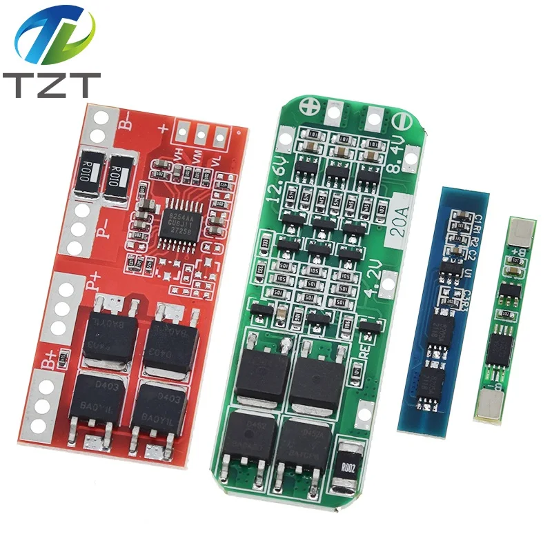
4 Channel 5V relay module - bottom view
4 Channel 5V relay module - top view
本教程是……的一部分: 使用 Arduino 控制继电器
- Arduino Code and Video for a Dual-Channel 5V Relay
- Controlling a 5V Relay Using Arduino to cotrol AC or DC load like bulb or motor
- 使用5V继电器模块(低触发)与Arduino
- Using a MAX6675 K-Type Thermocouple with Relay and Display
- Using a Reed Switch to Control a Relay and AC/DC Loads with an Arduino
- Using a TTP223B touch module and relay to control AC/DC loads with an Arduino
- Using an Arduino push button to switch a relay and AC bulb
20-TTP224 4-Channel Capacitive Touch Arduino with Relay Code
语言: C++
This code has not been parsed yet. Please return to the admin panel to parse it.资源与参考
尚无可用资源。
文件📁
数据手册 (pdf)
-
TTP224 datasheet by Taiwan Semiconductor (TONTEK)
TTP224_datasheet.pdf0.29 MB