4-Channel Solid-State Relay with Arduino
This project guide demonstrates how to control a 4-channel solid-state relay (SSR) module using an Arduino. This setup allows you to switch up to four separate AC loads, such as bulbs or small appliances, without any mechanical contacts or audible clicking sounds. This is ideal for automating home lighting, creating smart power outlets, building industrial control panels, or managing heating elements in a safe and silent manner. By the end of this guide, you will understand the hardware, wiring, and code needed to bring your own AC control projects to life.
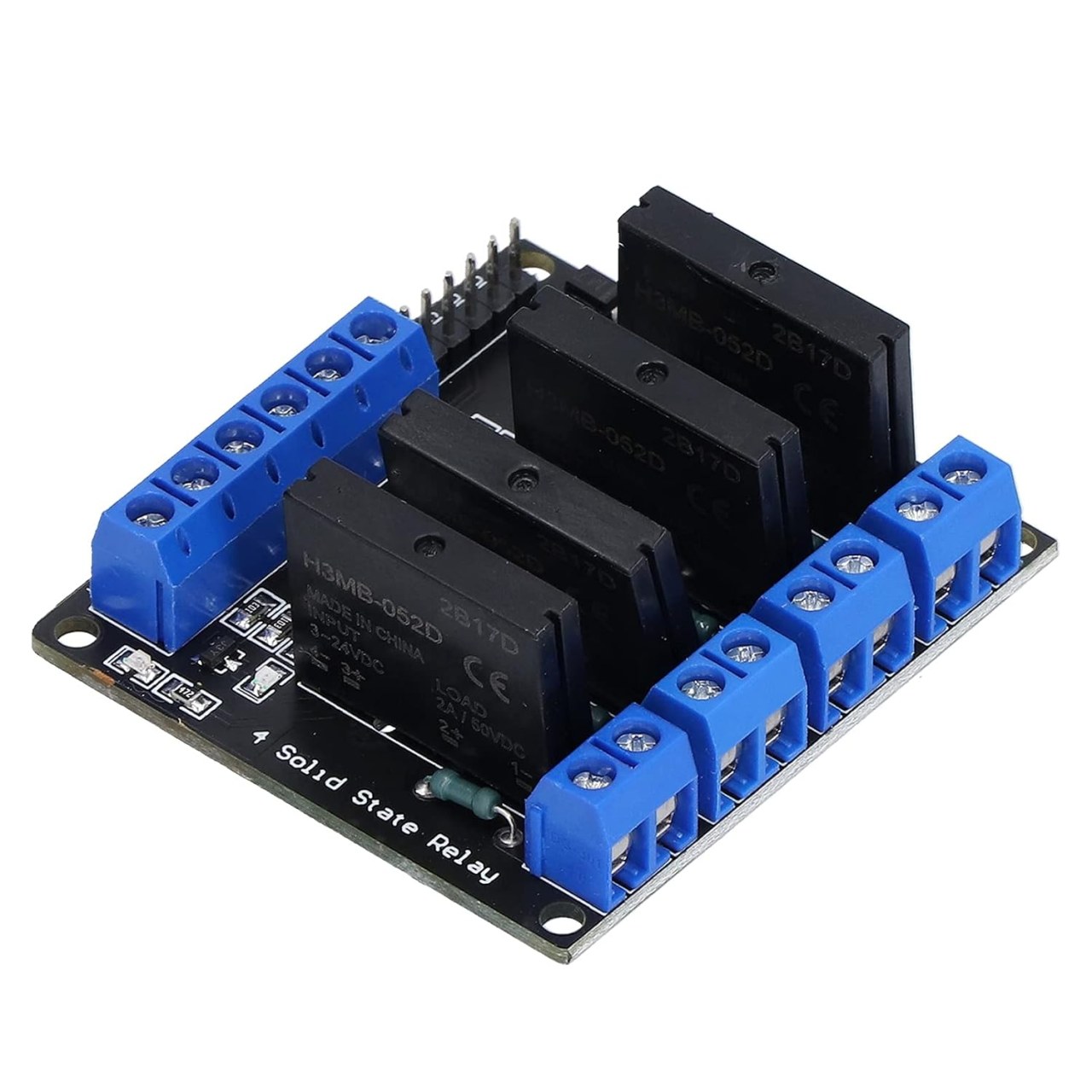
Hardware Components
- Arduino Uno (or compatible board)
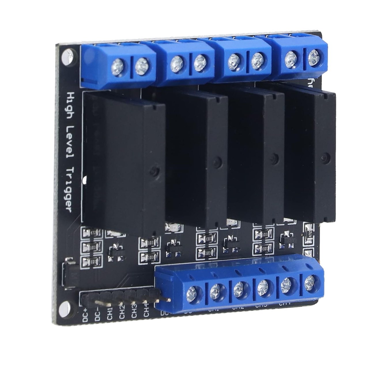
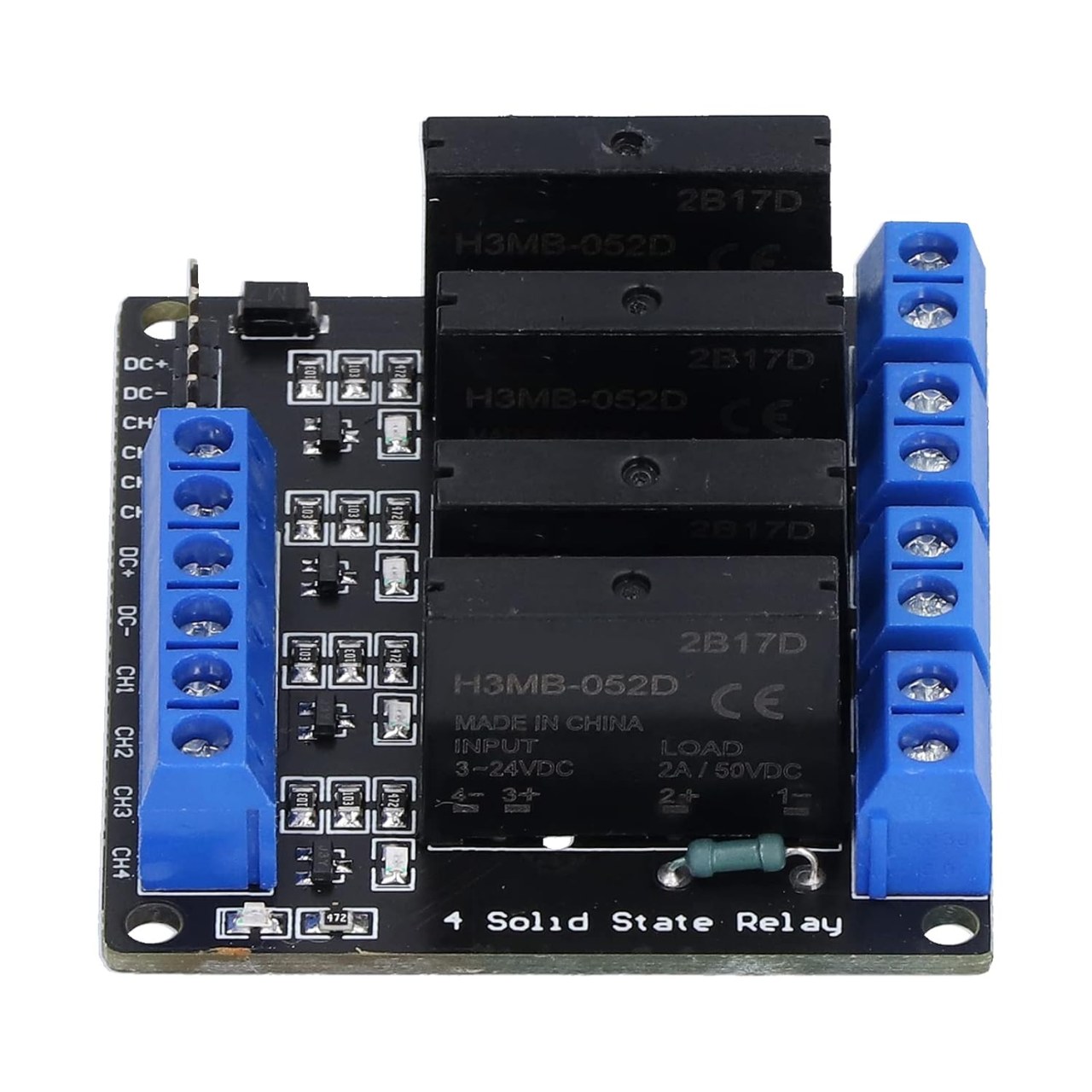
- 4-Channel Solid-State Relay Module (based on OMRON G3MB-202P)
- 4 AC Bulbs or other AC loads (within the module's rating)
- Jumper Wires (Dupont connectors recommended)
- AC Power Cord and Plug (for the load)
- Breadboard (optional, for prototyping)
Wiring Guide
Before you begin, it is critical to remember that you are working with dangerous AC mains voltage. Always disconnect the power before making any connections. Never touch the module or its connections while it is powered. Place the module on a non-conductive surface, such as plastic or wood, to prevent short circuits. (in video at 00:32)
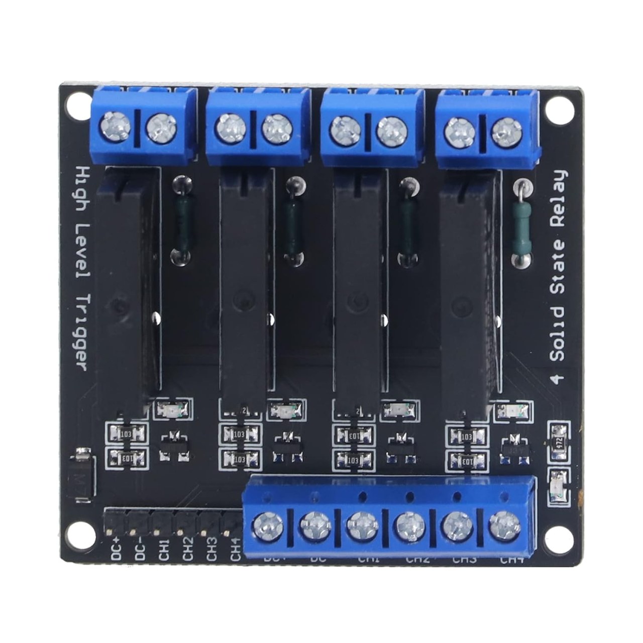
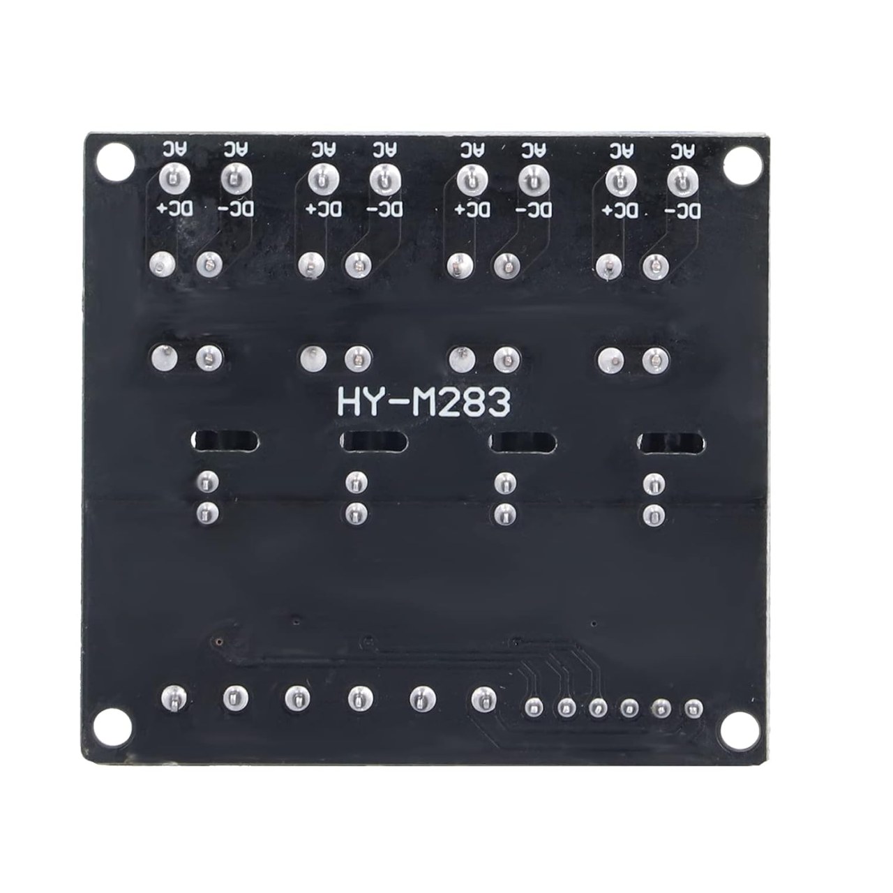
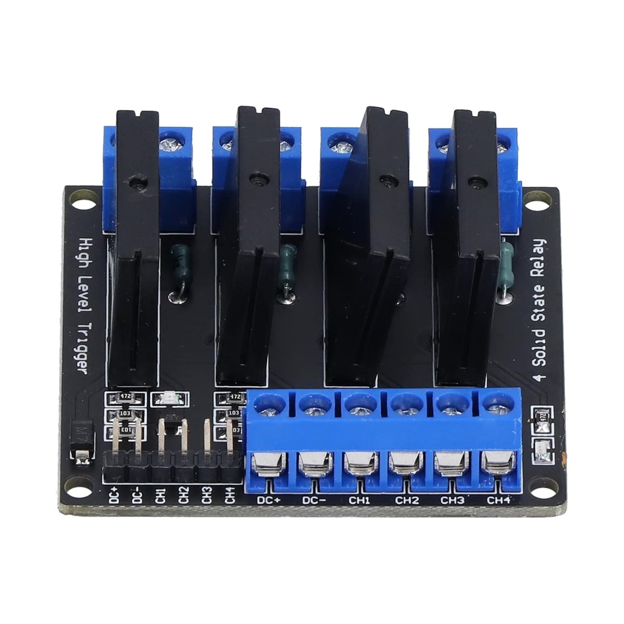
The wiring for this project is straightforward. The module has two sides: a low-voltage control side and a high-voltage load side. On the control side, you will find the DC+ and DC- pins for power, and four input pins labeled CH1, CH2, CH3, and CH4. These are connected to the Arduino as follows:
- DC+ to Arduino 5V
- DC- to Arduino GND
- CH1 to Arduino digital pin 2
- CH2 to Arduino digital pin 3
- CH3 to Arduino digital pin 4
- CH4 to Arduino digital pin 5
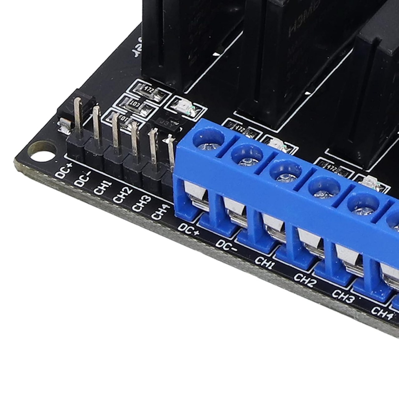
On the load side, each relay channel has two screw terminals. To connect a load, you must cut one of the wires from your AC power source and connect the two ends to these terminals. The relay acts as a switch, connecting or disconnecting the circuit. (in video at 04:12) For each of the four loads, you will connect its two wires to the corresponding channel's terminals. The diagram below illustrates this setup, with the Arduino pins on the left and the AC loads connected to the right.

Code Explanation
The Arduino code provided for this project is designed to be simple to configure. The key user-configurable parts are at the top of the sketch. (in video at 06:12)
First, you define the pins connected to the relay module:
int ssr[]={2,3,4,5}; // Arduino pin numbers used for SSRNext, you must set the trigger type to match your specific module. The code supports both high-trigger and low-trigger modules. If you are unsure which type you have, check the label on the module or its product listing. (in video at 06:48)
int triggerType = HIGH;// type LOW if low trigger and HIGH if high trigger SSR is usedFinally, you can adjust the default delay time used in the demonstration loop:
int wait = 2000;// delay timeThe code includes a custom function, contrlSSR(), which simplifies controlling each relay. To use it, you provide three parameters: the relay number (1-4), the action (ssrON or ssrOFF), and the duration in milliseconds to hold that state. For example, contrlSSR(1, ssrON, 5000); will turn on relay 1 for 5 seconds. This function handles the logic of translating your high-level commands into the correct digital signals for your specific trigger type. (in video at 08:58)
Live Project Demonstration
In the demonstration, the code is first run to show a basic on/off sequence for a single channel. You can see the LED on the module light up as the corresponding AC bulb turns on. (in video at 12:31) The code is then modified to demonstrate controlling multiple channels in a sequence, turning them on and off one by one. This showcases the flexibility of the setup for creating various automation patterns. (in video at 12:51) Finally, a loop is used to cycle through all four channels, turning each on and then off in sequence. (in video at 13:12)
Chapters
- [00:00] Introduction to the 4-Channel SSR Project
- [00:32] Safety Warnings for Working with AC
- [01:10] Understanding the SSR Module Specifications
- [02:18] Module Pinout and Connectors
- [04:12] Preparing and Connecting AC Loads
- [05:34] Wiring the Module to the Arduino
- [06:12] Code Configuration and Explanation
- [08:58] Using the contrlSSR() Function
- [12:31] Live Demonstration and Testing
- [14:01] Conclusion and Additional Resources
이미지
++
/*
 * This is code to control 4-channel Solid State Relay (SSR) modules using Arduino.
 * Written by Ahmad Shamshiri for Robojax.com
 * on January 11, 2019 at 21:03 in Ajax, Ontario, Canada.

  Watch instruction video for this code: https://youtu.be/Rfaz5qOLKYQ

 * This code is "AS IS" without warranty or liability. Free to be used as long as you keep this note intact.
 * This code has been downloaded from Robojax.com
    This program is free software: you can redistribute it and/or modify
    it under the terms of the GNU General Public License as published by
    the Free Software Foundation, either version 3 of the License, or
    (at your option) any later version.

    This program is distributed in the hope that it will be useful,
    but WITHOUT ANY WARRANTY; without even the implied warranty of
    MERCHANTABILITY or FITNESS FOR A PARTICULAR PURPOSE.  See the
    GNU General Public License for more details.

    You should have received a copy of the GNU General Public License
    along with this program.  If not, see <https://www.gnu.org/licenses/>.
 */


int ssr[]={2,3,4,5}; // Arduino pin numbers used for SSR
int triggerType = HIGH;// type LOW if low trigger and HIGH if high trigger SSR is used
int wait = 2000;// delay time

int ssrON, ssrOFF;// used for two different SSR trigger type. Do not change

void setup() {

    Serial.begin(9600);// prepare Serial monitor
    // set pins as output
    if(triggerType)
    {
      ssrON = HIGH;
      ssrOFF = LOW;
    }else{
      ssrON = LOW;
      ssrOFF = HIGH;
    }
 for(int i=0; i < 4; i++)
 {
    pinMode(ssr[i], OUTPUT);// sent i(th) pin as output
    digitalWrite(ssr[i], ssrOFF); // Turn the SSR OFF
 }

    Serial.println("Robojax 4 SSR ");


}

void loop() {

  // this is just a demo
 for(int i=0; i < 4; i++)
 {
      contrlSSR(i+1, ssrON, 2000); // turn SSRs one by one ON
 }// for loop


 for(int i=0; i < 4; i++)
 {
      contrlSSR(i+1, ssrOFF, 1000);  // turn SSRs one by one OFF
 }// for loop


   contrlSSR(1, ssrON, 2000);  // turn SSR1 ON for 2 seconds
   contrlSSR(2, ssrON, 3000);// turn SSR2 ON for 3 seconds
   contrlSSR(4, ssrON, 2000);// turn SSR4 ON for 2 seconds

   contrlSSR(1, ssrOFF, 0); // turn ssr1 OFF
   contrlSSR(4, ssrOFF, 0);// turn ssr4 OFF
   contrlSSR(2, ssrOFF, 0);// turn ssr2 OFF

   delay(2000);
    Serial.println("====== loop done ==");

}// loop


/*

 *  contrlSSR turns OFF or ON SSR
 *  January 11, 2019
 * @param  is an integer, SSR number starts with 1
 * @param control should be ssrON or ssrOFF
 * @param wait is a number in milliseconds.

 *
 */
void contrlSSR(int number, int control, int wait)
{
  if(control == HIGH)
  {
     Serial.print("SSR "); Serial.print(number);Serial.println(" ON");
      digitalWrite(ssr[number-1], ssrON); // Turn the SSR ON
      delay(wait);
  }else{
     Serial.print("SSR "); Serial.print(number);Serial.println(" OFF");
      digitalWrite(ssr[number-1], ssrOFF); // Turn the SSR OFF
      delay(wait);
  }
}
필요할 수 있는 것들
-
아마존Solid State relay on Amazonamzn.to
-
이베이
-
알리익스프레스Solid State relay 1ch 2ch 4ch and 8ch on AliExpresss.click.aliexpress.com
-
알리익스프레스Solid State relay 1ch 2ch 4ch and 8ch on AliExpress-2s.click.aliexpress.com
자원 및 참고자료
아직 자원이 없습니다.
파일📁
프리징 파일
-
Solid State High Level Relay Module
Solid State High Level Relay Module .fzpz0.04 MB
다른 파일들
-
Datasheet for GM3B solid state relay
robojax-solid-state-relay_G3MB.pdf0.31 MB