Dieses Tutorial ist Teil von: Tastaturen
Alle Videos zu Tastaturen sind hier aufgelistet.

1602 LCD Keypad Shield: Basic Code
In this tutorial, we will explore how to program and utilize a 1602 LCD Keypad Shield with an Arduino. This shield features a 16-character by 2-line display and a keypad that allows for various input functionalities. By the end of this guide, you will be able to display messages and respond to key presses effectively.
The focus will be on creating a simple program that detects key presses and displays corresponding messages on the LCD. You can follow along with the video for a visual demonstration (in video at 03:00).
Hardware Explained
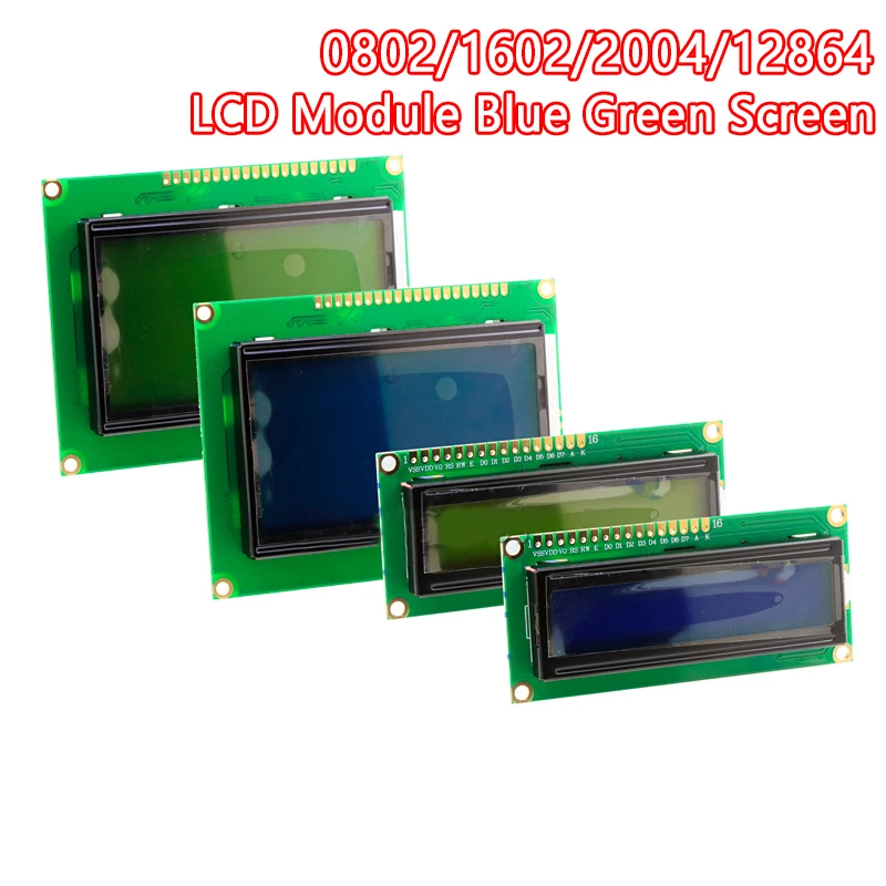
The primary component in this build is the 1602 LCD Keypad Shield. This shield connects directly to the Arduino board and provides both a display and a keypad for user interaction. The LCD can show text messages, while the keypad allows users to select options through various buttons.
The keypad operates using an analog input, which the Arduino reads to determine which button is pressed. Each button has a unique resistance, allowing the microcontroller to identify the button based on the analog value received from the sensor.
Datasheet Details
| Manufacturer | Generic |
|---|---|
| Part number | 1602 LCD Keypad Shield |
| Logic/IO voltage | 5 V |
| Supply voltage | 5 V |
| Output current (per channel) | 2 mA |
| Peak current (per channel) | 20 mA |
| PWM frequency guidance | N/A |
| Input logic thresholds | 0.3 Vcc to 0.7 Vcc |
| Voltage drop / RDS(on) / saturation | N/A |
| Thermal limits | 70 °C |
| Package | Shield format |
| Notes / variants | Compatible with Arduino Uno |
- Ensure the LCD is powered at 5 V to avoid damage.
- Use proper pull-up resistors for the keypad if needed.
- Debounce key presses in the code to avoid multiple triggers.
- Keep an eye on the current limits to avoid overheating.
- Test connections before powering the circuit.
Wiring Instructions
To wire the 1602 LCD Keypad Shield, simply plug it directly into the Arduino board. The shield is designed to align with the pin configuration of an Arduino Uno. Ensure the pins are securely connected.
The keypad buttons connect to the analog input pin A0. The LCD data lines are handled internally by the library used, so you won't need to wire them separately. The shield also uses a few digital pins for controlling the backlight and other functionalities, which are pre-defined in the library. If you follow the library documentation, you'll find that it typically handles these connections automatically.
Code Examples & Walkthrough
In the code, we first include the necessary library for controlling the LCD:
#include <LCD4Bit_mod.h>This library facilitates communication with the 1602 LCD. We then create an instance of the LCD object with the number of lines specified.
Next, we initialize the LCD in the setup() function:
lcd.init();This line prepares the LCD for use. After initialization, we can display a test message using the lcd.printIn() function.
In the main loop, we read the analog input to detect key presses:
adc_key_in = analogRead(0);This line reads the value from the keypad. The value helps determine which key was pressed using the get_key() function that converts the ADC value into a key number.
Demonstration / What to Expect
When you run the code, pressing the buttons will display messages corresponding to the key pressed on the LCD. For example, pressing the right key will show "Right Key OK" on the display (in video at 05:30). If the key detection is not functioning correctly, check the wiring and ensure the correct libraries are included in your Arduino IDE.
Video Timestamps
- 00:00 - Introduction
- 03:00 - Code Overview
- 05:30 - Key Press Demonstration
Dieses Tutorial ist Teil von: Tastaturen
- Verwendung eines 4x3-Tastenfelds mit Arduino
- Arduino-Code und Video für ein Vier-Tasten-Keypad
- Arduino-Code und Video: Schwarzes 4x4-Matrix-Keypad
- Build a Simple Electronic Lock with Keypad and LCD Using Arduino
- Controlling an 8-channel relay with a 4x3 keypad
- Wie man ein 4x4-Soft-Keypad mit Arduino verwendet
- How to Use a 5x4 20-Key Keypad with Arduino to Detect Strings
- Lesson 67: Controlling an 8-Channel Relay with a Keypad Using Arduino
/*
 * // Beispielverwendung der LCD4Bit_mod Bibliothek
 * // Heruntergeladen von https://github.com/douggilliland/lb-Arduino-Code/tree/master/libraries/LCD4Bit_mod
 * // 1. Oktober 2017. Dieses Beispiel funktioniert mit einem 1602 LCD-Tastaturschild.
 * // Code verwendet für ein YouTube-Video für den Robojax-Kanal
 * // Sehen Sie sich das Video an https://youtu.be/naSSiS_9rEw
 */
#include <LCD4Bit_mod.h>
 // Erstellen Sie ein Objekt, um ein LCD zu steuern.
 // Anzahl der Zeilen im Display = 1
LCD4Bit_mod lcd = LCD4Bit_mod(2);

 // Kernbotschaften
char msgs[5][15] = {"Right Key OK ",
                    "Up Key OK    ",
                    "Down Key OK  ",
                    "Left Key OK  ",
                    "Select Key OK" };
int  adc_key_val[5] ={30, 150, 360, 535, 760 };
int NUM_KEYS = 5;
int adc_key_in;
int key=-1;
int oldkey=-1;

void setup() {
  pinMode(13, OUTPUT); // Wir werden die Debug-LED verwenden, um ein Herzschlag-Signal auszugeben.

  lcd.init();
 // Optional können Sie jetzt unsere anwendungsspezifischen Anzeigeeinstellungen einrichten, die zur Überschreibung dessen dienen, was das LCD in lcd.init() gemacht hat.
 // lcd.commandWrite(0x0F);// Cursor an, Display an, Blinken an. (Gemein!)
   lcd.clear();
  lcd.printIn("Robojax.com Testing");

}

void loop() {

	adc_key_in = analogRead(0); // Lese den Wert vom Sensor.
  digitalWrite(13, HIGH);
  key = get_key(adc_key_in); // In Tastendruck umwandeln

	if (key != oldkey) // Wenn ein Tastendruck erkannt wird
	{
    delay(50); // Warte auf die Entprellzeit
		adc_key_in = analogRead(0); // Lese den Wert vom Sensor.
    key = get_key(adc_key_in); // In Tastendruck umwandeln
    if (key != oldkey)
    {
      oldkey = key;
      if (key >=0){
      lcd.cursorTo(2, 0); // Linie = 2, x = 0
  			lcd.printIn(msgs[key]);
      }
    }
  }

 // delay(1000);
  digitalWrite(13, LOW);


}

 // ADC-Wert in Tastennummer umwandeln
int get_key(unsigned int input)
{
	int k;

	for (k = 0; k < NUM_KEYS; k++)
	{
		if (input < adc_key_val[k])
		{

    return k;
        }
	}

    if (k >= NUM_KEYS)
        k = -1; // Keine gültige Taste gedrückt

    return k;
}
Ressourcen & Referenzen
-
ExternArduion Bibliothek LCD4Bit_mod (getHub)github.com
Dateien📁
Keine Dateien verfügbar.