Arduino code to use an NJK-5002C Hall sensor
Introduction
This guide demonstrates how to build a magnetic field detection system using an NJK-5002C Hall effect sensor and an Arduino. The project shows how to use a magnet to trigger a relay, which then controls an AC load, such as a light bulb or a fan. This is a practical and safe way to automate AC-powered devices using a low-voltage control signal.
The core idea is that a Hall sensor detects the presence of a magnetic field. When a magnet (specifically, its South Pole) comes close to the sensor, it outputs a low signal. An Arduino reads this signal and activates a relay module. The relay acts as a switch, connecting or disconnecting the AC power to your load. This setup is a fundamental building block for many automation projects.
Here are a few practical project ideas you can build with this technology:
- Automated Lighting: Turn on a light when a door or window with a magnet is opened.
- Security Alarm: Trigger an alarm or a light when a magnetic contact is broken.
- Production Line Counting: Count items on a conveyor belt as they pass a sensor with a magnet attached.
- Position Detection: Detect the position of a robotic arm or a machine part that has a magnet attached.
- Safety Interlock: Cut power to a machine when a safety guard is opened.
Hardware Required
- Arduino Uno (or any compatible board)
- NJK-5002C Hall Effect Sensor
- Relay Module (5V)
- AC Load (e.g., a light bulb or small fan)
- Power Cord for AC Load
- Jumper Wires
- Magnet (with a clearly marked South Pole)
Wiring Guide
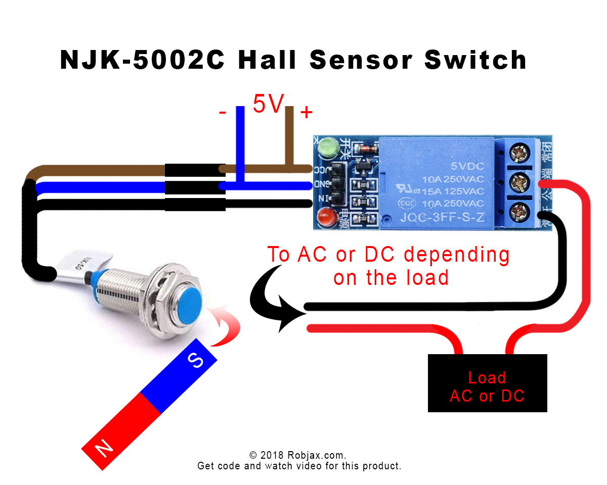
The wiring for this project is straightforward. The sensor and the relay module are both powered from the Arduino's 5V and GND pins. The signal from the sensor is read on a digital input pin, and the relay is controlled by a digital output pin.
Here is a breakdown of the connections:
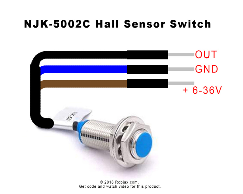
- NJK-5002C Sensor:
- Brown Wire → Arduino 5V
- Blue Wire → Arduino GND
- Black Wire → Arduino Digital Pin 2
- Relay Module:
- VCC Pin → Arduino 5V
- GND Pin → Arduino GND
- IN (or Signal) Pin → Arduino Digital Pin 8
- AC Load:
- Cut one wire of your AC load's power cord.
- Connect one end of the cut wire to the relay's Normally Open (NO) terminal.
- Connect the other end of the cut wire to the relay's Common (COM) terminal.
(in video at 05:09) The diagram below illustrates these connections. Note that the relay is a low-trigger type, meaning it activates when the signal pin is set to LOW.
Code Explanation
The Arduino code for this project is simple and focuses on reading the sensor and controlling the relay. The key parts of the code that you can configure are at the top of the sketch.
#define sensorPin  2 // pin 2
#define relayPin 8 // pin

const int wait = 3000;// after switched ON, wait for this amount of time
#define sensorPin 2: This defines the Arduino digital pin that is connected to the black wire of the Hall sensor. You can change this to any available digital pin.#define relayPin 8: This defines the Arduino digital pin connected to the IN pin on the relay module. You can change this to any available digital pin.const int wait = 3000;: This is a very important variable. It sets the amount of time in milliseconds that the relay will stay ON after the magnet is detected. In the video, it is set to 3000 ms (3 seconds). If you want the relay to turn off immediately when the magnet is removed, set this to0. (in video at 08:15)
The code also uses a delay(300) at the end of the main loop. This is a debounce delay to prevent rapid, unintended on/off switching. You can adjust this value, but a setting of 100 ms to 300 ms is generally good for stable operation. (in video at 11:03)
Live Project Demonstration
In the video demonstration, the system is shown working with an AC bulb. When the South Pole of a magnet is brought close to the sensor, the sensor's LED turns on, the Arduino reads a LOW signal, and it activates the relay. This connects the AC power to the bulb, turning it on. The serial monitor also prints "Sensed".
(in video at 11:19) It's crucial to note that the sensor is polarity-sensitive. It will only trigger with the South Pole of the magnet. The North Pole will not be detected. Furthermore, the magnet needs to be very close and properly aligned with the sensor's face for reliable detection. The demonstration highlights that the sensor does not work from the side or at a distance.
Chapters
- [00:00] Introduction and Project Overview
- [00:39] NJK-5002C Sensor Specifications
- [02:44] Relay Module and Wiring Setup
- [05:09] Full Wiring Diagram and AC Load Connection
- [07:55] Code Explanation
- [11:19] Live Demonstration and Testing
- [13:30] Conclusion and Final Tips
Images
++
/*
 * This is the Arduino code to use NJK-5002C hall sensor to control a DC or AC load.
 * In the video, I have explained that this can be used without Arduino and with Arduino.
 * Watch video instructions on YouTube: https://youtu.be/7RQ8QoJWhpY
 *
 *
 * Written by Ahmad Shamshiri for Roboja Video, www.Robojax.com
 * Date: November 10, 2018, Saturday at 09:34 in Ajax, Ontario, Canada
 * Please keep this note with the code.
 * This code is available on Robojax.com
 *
 * This code is "AS IS" without warranty or liability. Free to be used as long as you keep this note intact.
 * This code has been downloaded from Robojax.com
    This program is free software: you can redistribute it and/or modify
    it under the terms of the GNU General Public License as published by
    the Free Software Foundation, either version 3 of the License, or
    (at your option) any later version.

    This program is distributed in the hope that it will be useful,
    but WITHOUT ANY WARRANTY; without even the implied warranty of
    MERCHANTABILITY or FITNESS FOR A PARTICULAR PURPOSE.  See the
    GNU General Public License for more details.

    You should have received a copy of the GNU General Public License
    along with this program.  If not, see <https://www.gnu.org/licenses/>.
 */

#define sensorPin  2 // pin 2
#define relayPin 8 // pin

const int wait = 3000;// after switched ON, wait for this amount of time

void setup() {

  // Robojax.com 20181110 NJK-5002C hall sensor
  pinMode(sensorPin, INPUT_PULLUP);// define pin as input for sensor
  // watch video explaining the INPUT_PULLUP
  //https://robojax.com?vid=robojax-push_botton_resistor

  pinMode(relayPin, OUTPUT);// define pin as output

  Serial.begin(9600);// initialize serial monitor with 9600 baud.
}

void loop() {
  // Robojax.com 20181110 NJK-5002C hall sensor
  int sensed = digitalRead(sensorPin);// read pin 2 and put the result in the "sensed" variable
  if(sensed == LOW){
    Serial.println("Sensed");
    digitalWrite(relayPin, LOW);// if sensed turn relay ON
    delay(wait);// keep the relay ON for the "wait" amount of time
  }else{
    digitalWrite(relayPin, HIGH);// else turn the relay OFF
    Serial.println("====");
  }
 delay(300);// delay for 0.3 seconds
  // Robojax.com 20181110 NJK-5002C hall sensor
}
Things you might need
-
Amazon
-
eBay
-
eBayPurchase NKJ-5002C from eBayebay.us
-
AliExpressPurchase NKJ-5002C from AliExpresss.click.aliexpress.com
Resources & references
No resources yet.
Files📁
No files available.