RoboJax Touch Counter V2 Using LCD1602-I2C Display
Introduction
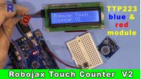
This guide will show you how to build a simple yet highly functional touch counter using an Arduino Uno, a TTP223B capacitive touch sensor, and an I2C-enabled LCD1602 display. This project, known as the Robojax Touch Counter V2, is a perfect starting point for anyone looking to add intuitive, touch-based input to their electronics projects. Instead of a mechanical button, a simple touch on the sensor's pad increments a counter, with the current count displayed clearly on the LCD screen. A separate push button allows you to reset the count back to zero at any time.


This project is not just a learning exercise; it has a wide range of practical applications. Here are a few ideas to inspire you:
- People Counter: Create a simple device to count the number of people entering a room or a specific area.
- Production Line Counter: Use it to tally items as they pass a point on a small conveyor belt or assembly process.
- Attendance Tracker: Build a simple system for tracking attendance at a class or event.
- Interactive Art Installation: Use it as a component in an art piece that reacts to the number of times it is touched.
- Educational Tool: Teach the basics of sensors, interrupts, and display interfaces in a fun, hands-on way.
By the end of this guide, you'll have a fully working touch counter and a solid understanding of how to integrate touch sensors, I2C displays, and user input into your own Arduino projects.
Hardware Components
To build this project, you will need the following components:
- Arduino Uno (or compatible board)
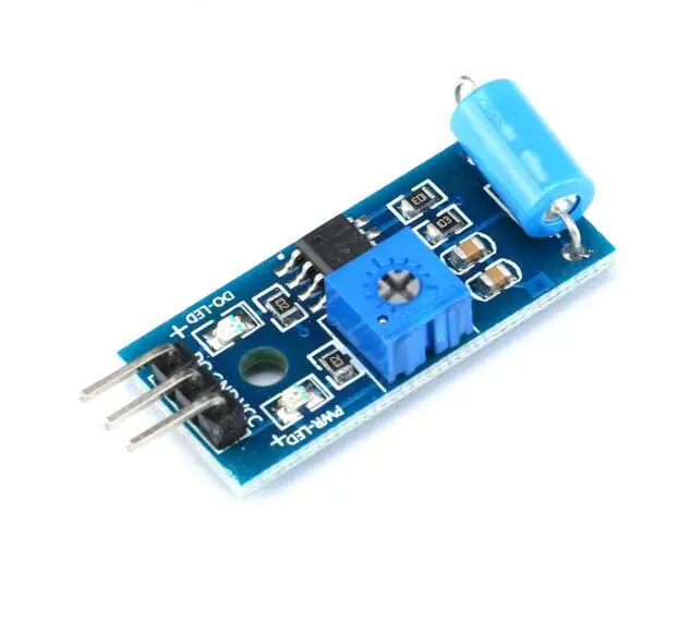
- TTP223B or TTP223 Capacitive Touch Sensor Module (Red or Blue variant)
- LCD1602 Display with I2C Interface Module
- Push Button (for reset)
- Jumper Wires
- Breadboard
Wiring Guide
The wiring for this project is straightforward, but it's important to note that the pin order on the red and blue touch modules is different. Here is a breakdown of how to connect everything.
First, let's connect the touch sensor. For the blue module, the pin order is Signal, VCC, and Ground. Connect the Signal pin to Arduino pin 2, VCC to 5V, and Ground to GND. For the red module, the pin order is Ground, Signal, and VCC (in video at 02:57). Connect the Ground pin to GND, the Signal (middle) pin to Arduino pin 2, and the VCC pin to 5V (in video at 03:01).
Next, connect the LCD display. The I2C interface uses only four wires. Connect the GND pin on the display to Arduino GND, the VCC pin to 5V, the SDA pin to Arduino's analog pin A4, and the SCL pin to Arduino's analog pin A5 (in video at 03:55). These are the correct pins for the Arduino Uno. If you are using a different board like an Arduino Mega, the SDA and SCL pins are on 20 and 21 respectively (in video at 04:18).
Finally, connect the reset push button. Place the button on the breadboard and connect one of its pins to Arduino GND and the other to Arduino pin 12 (in video at 03:33). The order of these wires does not matter.
This project does not require any resistors for the touch sensor or the button, as the code will use the Arduino's internal pull-up resistor for the button.
Code Explanation
The code for this project is designed to be simple to understand and modify. The key user-configurable parts are located at the top of the sketch.
Here is the section of the code you will most likely want to customize:
// start of settings for LCD1602 with I2C
#include <Wire.h>
#include <LiquidCrystal_I2C.h>
// Set the LCD address to 0x27 for a 16 chars and 2 line display
LiquidCrystal_I2C lcd(0x27, 16, 2);
// end of settings for LCD1602 with I2C

const int touchPin = 2;// the input pin where touch sensor is connected
const int resetPin = 12;// the input pin for reset button
const int touchDelay = 500;//millisecond delay between each touch

int count=0;// variable holding the count number
Let's break down what each of these settings does:
- LCD Address: The
lcd(0x27, 16, 2)line sets up the display. The0x27is the I2C address of your specific LCD module. Most modules use this address, but if your display doesn't work, it might be0x3F. You can change this value to match your display. - touchPin: This constant defines the Arduino pin to which the signal wire of your touch sensor is connected. You can change this if you want to use a different pin.
- resetPin: This constant defines the Arduino pin for your reset button. It's set to pin 12 by default.
- touchDelay: This is a crucial setting. It controls the minimum time in milliseconds between two registered touches (in video at 05:13). A value of 500ms prevents accidental multiple counts from a single touch or from very quick taps. If you want the counter to be more responsive, you can reduce this value to something like 100ms (in video at 10:31).
The count variable is an integer that holds the current count value. It is initialized to zero and is incremented each time the sensor is touched. The code itself handles the logic of reading the sensor, updating the display, and checking the reset button, so you don't need to worry about that. Simply adjust the constants above to fit your specific setup and desired behavior.
Live Project Demonstration
Once you have everything wired up and the code uploaded to your Arduino, the project will work as follows:
When you power the device, the LCD will display "Robojax Touch" and "Counter V2" for a few seconds before it starts counting. Each time you touch the sensor pad, the counter will increment by one, and the new count will be displayed on the bottom line of the LCD, next to the word "Touched:" (in video at 07:51). The same information is also printed to the Arduino IDE's Serial Monitor for debugging or logging purposes.
To reset the counter, simply press the push button. The LCD will clear and display "Resetted", and the count will return to zero (in video at 08:49). The device is now ready to count again. This simple and clear feedback loop makes it easy to see the project working in real-time.
Chapters
- [00:00] Introduction and Project Overview
- [00:44] Components and How They Work
- [02:30] Wiring Guide for the Touch Sensor and Button
- [03:41] Wiring Guide for the LCD Display
- [04:26] Code Explanation and Setup
- [06:47] Understanding the Main Loop and Touch Logic
- [09:25] Live Demonstration and Testing
- [11:08] Conclusion and Future Project Ideas
Images

//*
 * This is Arduino touch counter V2 using TTP223/TTP223B and LCD1602-I2C
 * This program will function as a counter. Every time the touch module is touched,
 * the counter increments by 1. The count number is displayed on the LCD1602 display.
 * We have a reset button to restart the counting from zero.
 *
 * Watch video instruction for this video: https://youtu.be/5A9jPD5nUCw
 *
 * Written by Ahmad Shamshiri on Saturday, 27th of October at 16:28 in Ajax, Ontario, Canada
 * Get this code from Robojax.com
 *
 * This code is "AS IS" without warranty or liability. Free to be used as long as you keep this note intact.
 * This code has been downloaded from Robojax.com
    This program is free software: you can redistribute it and/or modify
    it under the terms of the GNU General Public License as published by
    the Free Software Foundation, either version 3 of the License, or
    (at your option) any later version.

    This program is distributed in the hope that it will be useful,
    but WITHOUT ANY WARRANTY; without even the implied warranty of
    MERCHANTABILITY or FITNESS FOR A PARTICULAR PURPOSE.  See the
    GNU General Public License for more details.

    You should have received a copy of the GNU General Public License
    along with this program.  If not, see <https://www.gnu.org/licenses/>.
 */

// start of settings for LCD1602 with I2C
#include <Wire.h>
#include <LiquidCrystal_I2C.h>
// Set the LCD address to 0x27 for a 16 chars and 2 line display
LiquidCrystal_I2C lcd(0x27, 16, 2);
// end of settings for LCD1602 with I2C

const int touchPin = 2;// the input pin where touch sensor is connected
const int resetPin = 12;// the input pin for reset button
const int touchDelay = 500;//millisecond delay between each touch

int count=0;// variable holding the count number

void setup() {
 // Robojax.com Touch counter 20181027
  // initialize the LCD
  lcd.begin();
  lcd.backlight();// turn the backlight ON for the LCD
      lcd.print("Robojax Touch");
      lcd.setCursor(0,1);
      lcd.print("Counter V2");
  Serial.begin(9600);// initialize serial monitor with 9600 baud
  Serial.println("Robojax Touch Counter V2");
  pinMode(touchPin,INPUT);// define a pin for touch module
  pinMode(resetPin,INPUT_PULLUP);// define a pin for reset button
  // see video ( link in the video description) on using PULLUP

  delay(3000);// give time to user to read the display at the beginning


  // Robojax.com Touch counter 20181027
}

void loop() {
  // Robojax.com Touch counter 20181027

  int touchValue = digitalRead(touchPin);// read touchPin and store it in touchValue

  // if touchValue is HIGH
  if(touchValue == HIGH)
  {
      count++;// increment the count

      lcd.clear();// clear previous values from screen
      lcd.print("Robojax  TCV2");
      lcd.setCursor(0,1);
      lcd.print("Touched:");
      lcd.setCursor(9,1);
      lcd.print(count);

      Serial.print("Touched ");//print the information
      Serial.print(count);//print count
      Serial.println(" times.");
    delay(touchDelay);// touch delay time
  }


   // if reset switch is pushed
   if(digitalRead(resetPin) == LOW)
   {
    lcd.clear();// clear previous values from screen
    count =0;// reset the counter;
      Serial.println("Counter Resetted.");//print the information
      lcd.setCursor(0,0);
      lcd.print("Robojax  TCV2");
      lcd.setCursor(0,1);
      lcd.print("Resetted");

   }

  // Robojax.com Touch counter 20181027
}
Things you might need
-
AmazonPurchase LCD1602-I2C from Amazonamzn.to
-
Amazon
-
eBayPurchase LCD1602-I2C from eBayebay.us
-
AliExpressPurchase 10pcs LCD1602-I2C from AliExpresss.click.aliexpress.com
-
AliExpressPurchase LCD1602-I2C from AliExpresss.click.aliexpress.com
Resources & references
Files📁
Fritzing File
-
LCD LCD1602-I2C module with 4 wires
LCD1602-I2C.fzpz0.01 MB
Other files
-
TP223 Datasheet
robojax-0492_TTP223_Datasheet.pdf0.24 MB -
TTP223B User manual
robojax-TTP223B_manual.pdf0.15 MB -
LCD1602 LiquidCrystal Library
robojax-LCD1602_LiquidCrystal.zip