લેસર ટાઇમ-ઓફ-ફ્લાઇટ VL53L0X સેન્સરનો ઉપયોગ કરીને Arduino સાથે અંતર માપવું
આ ટ્યુટોરિયલમાં, આપણે Arduino સાથે VL53L0X લેસર ટાઇમ-ઓફ-ફ્લાઇટ સેન્સરનો ઉપયોગ કરીને અંતર કેવી રીતે માપવું તે શોધીશું. આ સેન્સર ચોક્કસ અંતર માપન કરવાની મંજૂરી આપે છે અને તેને રોબોટિક્સ અથવા ઓટોમેશન સિસ્ટમ જેવા વિવિધ પ્રોજેક્ટ્સમાં સંકલિત કરી શકાય છે. આ ટ્યુટોરિયલના અંત સુધીમાં, તમે સેન્સર સેટ કરી શકશો, તેને યોગ્ય રીતે વાયર કરી શકશો, અને અંતર રીડિંગ્સ મેળવવા માટે જરૂરી કોડ લખી શકશો.
અમે જરૂરી હાર્ડવેર ઘટકો, વાયરિંગ સૂચનાઓ અને VL53L0X સેન્સરને સંચાલિત કરતા કોડની વિગતવાર સમજૂતી આવરી લઈશું. પ્રક્રિયાના વધુ દ્રશ્ય રજૂઆત માટે, સંકળાયેલ વિડિયો (વિડિયોમાં 00:15 પર) ચોક્કસપણે જુઓ.
હાર્ડવેર સમજાવ્યું
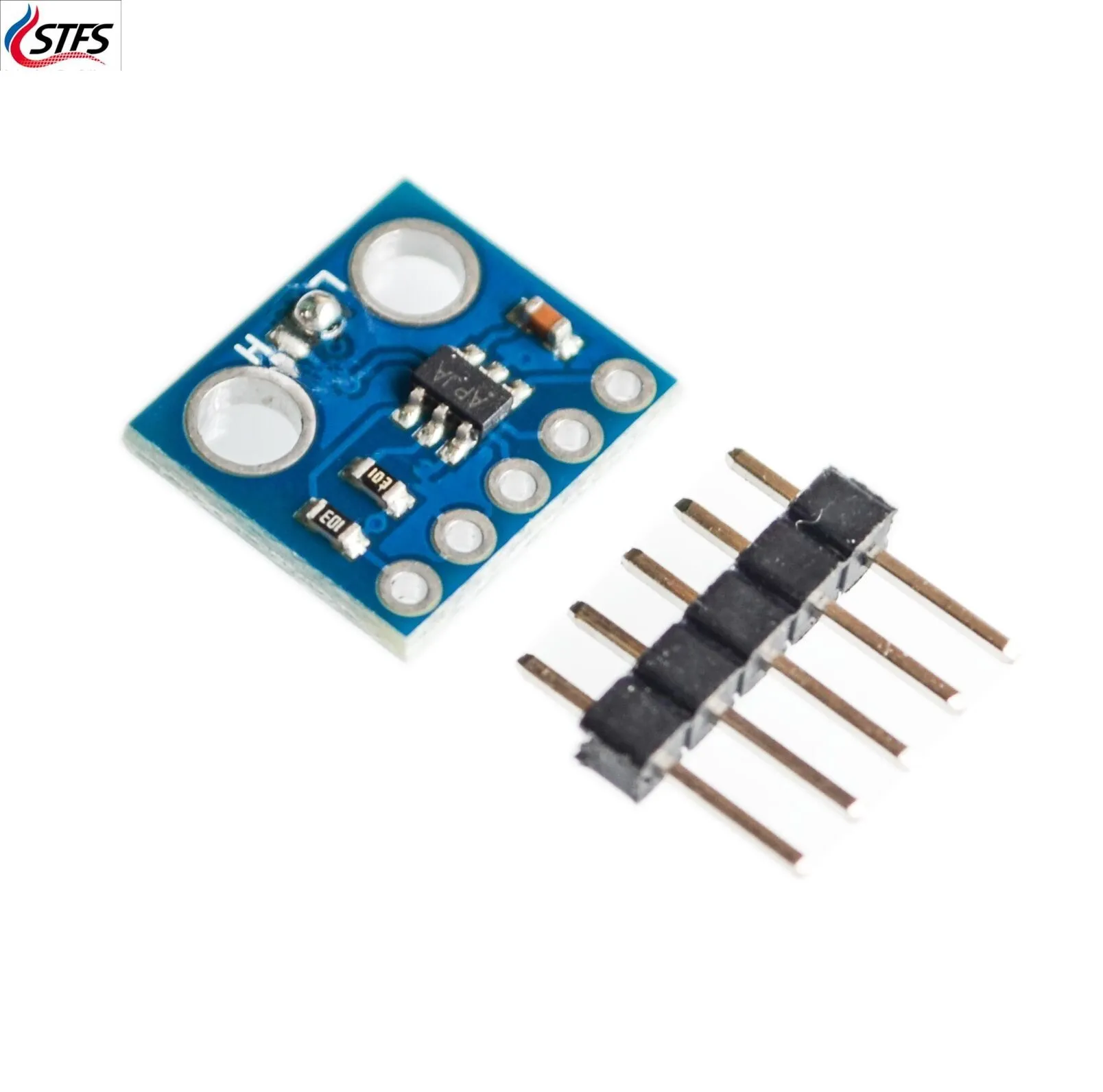
આ પ્રોજેક્ટનો મુખ્ય ઘટક VL53L0X સેન્સર છે. આ એક ટાઇમ-ઓફ-ફ્લાઇટ અંતર સેન્સર છે જે લેસર બીમ ઉત્સર્જિત કરીને અને પ્રતિબિંબિત પ્રકાશને સેન્સર પર પાછા આવવામાં લાગતો સમય માપીને કાર્ય કરે છે. તે મિલિમીટરમાં અંતર માપન પ્રદાન કરે છે અને અંતરની શ્રેણી પર કાર્ય કરવા સક્ષમ છે, જે તેને વિવિધ એપ્લિકેશનો માટે યોગ્ય બનાવે છે.
VL53L0X ઉપરાંત, સેન્સર ડેટા પ્રોસેસ કરવા માટે તમારે Arduino બોર્ડની જરૂર પડશે. Arduino I2C પ્રોટોકોલ દ્વારા સેન્સર સાથે વાતચીત કરશે, જે સરળ સંકલન અને નિયંત્રણ માટે પરવાનગી આપે છે. સેન્સર અને Arduino વચ્ચે જોડાણો સ્થાપિત કરવા માટે તમારે જમ્પર વાયરની પણ જરૂર પડશે.
ડેટાશીટ વિગતો
| ઉત્પાદક | STMicroelectronics |
|---|---|
| ભાગ નંબર | VL53L0X |
| લોજિક/IO વોલ્ટેજ | 1.8 V થી 3.6 V |
| સપ્લાય વોલ્ટેજ | 2.6 V થી 3.6 V |
| આઉટપુટ કરંટ (પ્રતિ ચેનલ) | … |
| પીક કરંટ (પ્રતિ ચેનલ) | … |
| PWM ફ્રીક્વન્સી માર્ગદર્શન | … |
| ઇનપુટ લોજિક થ્રેશોલ્ડ | … |
| વોલ્ટેજ ડ્રોપ / RDS(on) / સેચ્યુરેશન | … |
| થર્મલ મર્યાદાઓ | -40 °C થી 85 °C |
| પેકેજ | QFN-16 |
| નોંધો / વેરિઅન્ટ્સ | ટાઇમ-ઓફ-ફ્લાઇટ સેન્સર, I2C ઇન્ટરફેસ |
- સેન્સરને નુકસાન ન થાય તે માટે યોગ્ય વોલ્ટેજ સ્તરની ખાતરી કરો.
- જરૂર પડ્યે I2C લાઇનો પર પુલ-અપ રેઝિસ્ટરનો ઉપયોગ કરો.
- ચોક્કસ રીડિંગ્સ માટે સેન્સરને સ્વચ્છ અને અવરોધરહિત રાખો.
- ચોકસાઈ સુધારવા માટે ચોક્કસ વાતાવરણ માટે સેન્સરને કેલિબ્રેટ કરો.
- માપન સમસ્યાઓને નિયંત્રિત કરવા માટે કોડમાં ટાઇમઆઉટ ભૂલો તપાસો.
વાયરિંગ સૂચનાઓ
VL53L0X સેન્સરને Arduino સાથે વાયર કરવા માટે, સેન્સર પરના VCC પિનને Arduino પરના 5V પિન સાથે જોડીને શરૂ કરો. આ સલામત છે કારણ કે સેન્સરમાં આંતરિક રેગ્યુલેટર છે જે તેને 3.3V સ્તરે કાર્ય કરતી વખતે 5V સપ્લાય સાથે કાર્ય કરવાની મંજૂરી આપે છે. આગળ, સેન્સર પરના GND પિનને Arduino પરના ગ્રાઉન્ડ પિન સાથે જોડો.
હવે, સેન્સર પરના SDA પિનને Arduino પરના A4 પિન સાથે જોડો, જે ડિફોલ્ટ I2C ડેટા લાઇન છે. પછી, સેન્સર પરના SCL પિનને Arduino પરના A5 પિન સાથે જોડો, જે ડિફોલ્ટ I2C ક્લોક લાઇન છે. અન્ય Arduino મોડેલો માટે, SDA અને SCL પિન અલગ હોઈ શકે છે; ઉદાહરણ તરીકે, Arduino Mega પર, અનુક્રમે પિન 20 અને 21 નો ઉપયોગ કરો. સિસ્ટમ ચાલુ કરતા પહેલા બધા જોડાણો સુરક્ષિત છે તેની ખાતરી કરો.
કોડ ઉદાહરણો અને વોકથ્રુ
Arduino કોડમાં, અમે જરૂરી લાઇબ્રેરીઓ શામેલ કરીને અને VL53L0X સેન્સરને પ્રારંભ કરીને શરૂ કરીએ છીએ. setup() ફંક્શનમાં, અમે સીરિયલ કમ્યુનિકેશન સેટ કરીએ છીએ અને સેન્સરને પ્રારંભ કરીએ છીએ:
void setup() {
  Serial.begin(9600);
  Wire.begin();
  sensor.init();
  sensor.setTimeout(500);
  sensor.startContinuous();
}
આ સ્નિપેટ સેન્સરને પ્રારંભ કરે છે અને સતત માપન મોડ શરૂ કરે છે. setTimeout(500) ફંક્શન ખાતરી કરે છે કે જો સેન્સર અંતર વાંચવામાં નિષ્ફળ જાય તો તે અનિશ્ચિત સમય સુધી અટકી ન જાય.
loop() ફંક્શનમાં, અમે અંતર વાંચીએ છીએ અને તેને સીરિયલ મોનિટર પર છાપીએ છીએ:
void loop() {
  int distance = sensor.readRangeContinuousMillimeters();
  distance = distance - 55; // ભૂલ માટે વળતર આપો
  Serial.print("અંતર: ");
  Serial.print(distance);
  Serial.print("mm");
  if (sensor.timeoutOccurred()) { Serial.print(" ટાઇમઆઉટ"); }
  Serial.println();
}
કોડનો આ વિભાગ અંતર માપન મેળવે છે અને સતત મૂલ્ય બાદ કરીને કોઈપણ વ્યવસ્થિત ભૂલ માટે વળતર આપે છે. તે સેન્સર રીડિંગ મેળવવામાં નિષ્ફળ જાય તો ટાઇમઆઉટ પણ તપાસે છે.
પ્રદર્શન / શું અપેક્ષા રાખવી
જ્યારે તમે પ્રોગ્રામ ચલાવો છો, ત્યારે તમારે સીરિયલ મોનિટરમાં VL53L0X સેન્સર દ્વારા માપેલા અંતરના સતત અપડેટ્સ જોવા જોઈએ. રીડિંગ્સ મિલિમીટરમાં પ્રદર્શિત થશે. જો તમે કોઈ વસ્તુને સેન્સરની નજીક અથવા દૂર ખસેડો છો, તો અંતરના મૂલ્યો તે મુજબ બદલાશે. જો ટાઇમઆઉટ થાય, તો તમે "ટાઇમઆઉટ" સંદેશ જોશો જે દર્શાવે છે કે સેન્સર અંતર વાંચવામાં નિષ્ફળ ગયું છે (વિડિયોમાં 05:30 પર).
વિડિયો ટાઇમસ્ટેમ્પ્સ
- 00:00 - પરિચય
- 00:15 - ઘટકોની ઝાંખી
- 01:00 - વાયરિંગ સૂચનાઓ
- 02:30 - કોડ વોકથ્રુ
- 05:30 - પ્રદર્શન
/* This example shows how to use continuous mode to take
range measurements with the VL53L0X. It is based on
vl53l0x_ContinuousRanging_Example.c from the VL53L0X API.

The range readings are in units of mm.

Original source: https://github.com/pololu/vl53l0x-arduino
Modified by Ahmad Shamshiri for RoboJax.com
Date modified: Sep 26, 2017
*/


#include <Wire.h>
#include <VL53L0X.h>

VL53L0X sensor;

void setup()
{
  Serial.begin(9600);
  Wire.begin();

  sensor.init();
  sensor.setTimeout(500);

  // Start continuous back-to-back mode (take readings as
  // fast as possible).  To use continuous timed mode
  // instead, provide a desired inter-measurement period in
  // ms (e.g. sensor.startContinuous(100)).
  sensor.startContinuous();
}

void loop()
{
  int distance =sensor.readRangeContinuousMillimeters();
 distance = distance -55;// -55 is to compensate for error. Change or set it to zero to make it work for your sensor
  Serial.print("Distance: ");
  Serial.print(distance);
  Serial.print("mm");
  if (sensor.timeoutOccurred()) { Serial.print(" TIMEOUT"); }

  Serial.println();
}++
/* This example shows how to use continuous mode to take
range measurements with two VL53L0X sensors. It is based on
vl53l0x_ContinuousRanging_Example.c from the VL53L0X API.
The range readings are in units of mm.
Original source: https://github.com/pololu/vl53l0x-arduino
Modified by Ahmad Shamshiri for RoboJax.com
Date modified: June 06, 2018
Dennis from YouTube requested this code on June 06, 2018
*/
#include <Wire.h>
#include <VL53L0X.h>
VL53L0X sensor1;// define object for sensor 1
VL53L0X sensor2;// define object for sensor 2
void setup()
{
Serial.begin(9600);
Wire.begin();
sensor1.init();// initialize sensor 1
sensor1.setTimeout(500);// set time out for sensor 1
sensor2.init();// initialize sensor 2
sensor2.setTimeout(500);// set time out for sensor 2
// Start continuous back-to-back mode (take readings as
// fast as possible). To use continuous timed mode
// instead, provide a desired inter-measurement period in
// ms (e.g. sensor.startContinuous(100)).
sensor1.startContinuous();// measure continuously for sensor 1
sensor2.startContinuous();// measure continuously for sensor 2
}
void loop()
{
int distance1 =sensor1.readRangeContinuousMillimeters();// get distance for sensor 1
int distance2 =sensor2.readRangeContinuousMillimeters();// get distance for sensor 2
distance1 = distance1 -55;// -55 is to compensate for error. Change or set it to zero to make it work for your sensor
distance2 = distance2 -34;// -35 is to compensate for error. Change or set it to zero to make it work for your sensor
Serial.print("Distance 1: ");
Serial.print(distance1);// print distance from sensor 1
Serial.print("mm Distance 2: ");
Serial.print(distance2);// print distance from sensor 2
Serial.print("mm");
if (sensor1.timeoutOccurred()) { Serial.print(" TIMEOUT 1"); }
if (sensor2.timeoutOccurred()) { Serial.print(" TIMEOUT 2"); }
Serial.println();
}સંસાધનો અને સંદર્ભો
હજી સુધી કોઈ સંસાધનો નથી.
ફાઇલો📁
Fritzing ફાઇલ
-
Adafruit VL6180X Time of Flight Distance SensorFritzing part for the Adafruit VL6180X Time of Flight distance sensor. This sensor measures absolute distance up to 100mm and ambient light, communicating via I2C. Includes the sensor breakout board and pin connections for use in Fritzing projects.
Adafruit VL6180X Time of Flight Distance Sensor-1.fzpz0.02 MB -
Adafruit VL6180X Time of Flight Distance SensorFritzing part file for the Adafruit VL6180X Time of Flight distance sensor. This module measures absolute distance up to 100mm and ambient light, communicating over I2C. Includes the sensor breakout board with pins for power, ground, SDA, SCL, and interrupt.
Adafruit VL6180X Time of Flight Distance Sensor.fzpz0.02 MB
અન્ય ફાઇલો
-
Polou VL53L0X library
robojax-VL53L0X-polou-arduino-master.zip0.02 MB