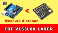
Measuring Distance with a Laser Time-of-Flight VL53L0X Sensor Using Arduino
In this tutorial, we will explore how to measure distances using the VL53L0X laser time-of-flight sensor with an Arduino. This sensor allows for precise distance measurements and can be integrated into various projects, such as robotics or automation systems. By the end of this tutorial, you will be able to set up the sensor, wire it correctly, and write the necessary code to obtain distance readings.
We will cover the hardware components required, wiring instructions, and a detailed explanation of the code that operates the VL53L0X sensor. For a more visual representation of the process, be sure to check out the associated video (in video at 00:15).
Hardware Explained
The primary component of this project is the VL53L0X sensor. This is a time-of-flight distance sensor that works by emitting a laser beam and measuring the time it takes for the reflected light to return to the sensor. It provides distance measurements in millimeters and is capable of operating over a range of distances, making it suitable for various applications.
In addition to the VL53L0X, you will need an Arduino board to process the sensor data. The Arduino will communicate with the sensor via the I2C protocol, which allows for easy integration and control. You will also require jumper wires to establish connections between the sensor and the Arduino.
Datasheet Details
| Manufacturer | STMicroelectronics |
|---|---|
| Part number | VL53L0X |
| Logic/IO voltage | 1.8 V to 3.6 V |
| Supply voltage | 2.6 V to 3.6 V |
| Output current (per channel) | … |
| Peak current (per channel) | … |
| PWM frequency guidance | … |
| Input logic thresholds | … |
| Voltage drop / RDS(on) / saturation | … |
| Thermal limits | -40 °C to 85 °C |
| Package | QFN-16 |
| Notes / variants | Time-of-flight sensor, I2C interface |
- Ensure proper voltage levels to avoid damaging the sensor.
- Use pull-up resistors on the I2C lines if necessary.
- Keep the sensor clean and unobstructed for accurate readings.
- Calibrate the sensor for specific environments to improve accuracy.
- Check for timeout errors in the code to handle measurement issues.
Wiring Instructions
To wire the VL53L0X sensor to the Arduino, start by connecting the VCC pin on the sensor to the 5V pin on the Arduino. This is safe because the sensor has an internal regulator that allows it to operate with a 5V supply while still functioning at 3.3V levels. Next, connect the GND pin on the sensor to the ground pin on the Arduino.
Now, connect the SDA pin on the sensor to the A4 pin on the Arduino, which is the default I2C data line. Then, connect the SCL pin on the sensor to the A5 pin on the Arduino, which is the default I2C clock line. For other Arduino models, the SDA and SCL pins may vary; for example, on the Arduino Mega, use pins 20 and 21, respectively. Ensure all connections are secure before powering on the system.
Code Examples & Walkthrough
In the Arduino code, we begin by including the necessary libraries and initializing the VL53L0X sensor. In the setup() function, we set up the serial communication and initialize the sensor:
void setup() {
  Serial.begin(9600);
  Wire.begin();
  sensor.init();
  sensor.setTimeout(500);
  sensor.startContinuous();
}
This snippet initializes the sensor and starts continuous measurement mode. The setTimeout(500) function ensures that the sensor will not hang indefinitely if it fails to read a distance.
In the loop() function, we read the distance and print it to the serial monitor:
void loop() {
  int distance = sensor.readRangeContinuousMillimeters();
  distance = distance - 55; // Compensate for error
  Serial.print("Distance: ");
  Serial.print(distance);
  Serial.print("mm");
  if (sensor.timeoutOccurred()) { Serial.print(" TIMEOUT"); }
  Serial.println();
}
This section of the code retrieves the distance measurement and compensates for any systematic error by subtracting a constant value. It also checks for timeouts in case the sensor fails to acquire a reading.
Demonstration / What to Expect
When you run the program, you should see continuous updates of the distance measured by the VL53L0X sensor in the serial monitor. The readings will display in millimeters. If you move an object closer or farther from the sensor, the distance values will change accordingly. If there's a timeout, you will see a "TIMEOUT" message indicating that the sensor failed to read the distance (in video at 05:30).
Video Timestamps
- 00:00 - Introduction
- 00:15 - Overview of components
- 01:00 - Wiring instructions
- 02:30 - Code walkthrough
- 05:30 - Demonstration
/*
 * هذا المثال يوضح كيفية استخدام وضع الاستمرار لأخذ قياسات المدى باستخدام VL53L0X. وهو مستند إلى vl53l0x_ContinuousRanging_Example.c من واجهة برمجة التطبيقات VL53L0X.
 *
 * قراءات المدى بوحدات مم.
 *
 * المصدر الأصلي: https://github.com/pololu/vl53l0x-arduino
 * معدل بواسطة أحمد شمشيري لموقع RoboJax.com
 * تاريخ التعديل: 26 سبتمبر 2017
 */
#include <Wire.h>
#include <VL53L0X.h>

VL53L0X sensor;

void setup()
{
  Serial.begin(9600);
  Wire.begin();

  sensor.init();
  sensor.setTimeout(500);

 // ابدأ وضع التشغيل المتواصل المتتابع (خذ قراءات كـ
 // بأسرع ما يمكن). لاستخدام الوضع المستمر المؤقت
 // بدلاً من ذلك، قدم فترة قياس متوسطة مرغوبة في
 // مللي ثانية (مثل sensor.startContinuous(100)).
  sensor.startContinuous();
}

void loop()
{
  int distance =sensor.readRangeContinuousMillimeters();
 distance = distance -55; // -55 هو لتعويض الخطأ. غيّر أو اضبطه على الصفر ليعمل مع المستشعر الخاص بك.
  Serial.print("Distance: ");
  Serial.print(distance);
  Serial.print("mm");
  if (sensor.timeoutOccurred()) { Serial.print(" TIMEOUT"); }

  Serial.println();
}
++
/*
 * يوضح هذا المثال كيفية استخدام الوضع المستمر لأخذ قياسات المدى باستخدام مستشعرين VL53L0X. وهو مستند إلى vl53l0x_ContinuousRanging_Example.c من واجهة برمجة التطبيقات VL53L0X.
 *
 * قراءات المدى بوحدات الملليمتر.
 *
 * المصدر الأصلي: https://github.com/pololu/vl53l0x-arduino
 * تم التعديل بواسطة أحمد شمشيري لموقع RoboJax.com
 * تاريخ التعديل: 6 يونيو 2018
 * طلب دينيس من يوتيوب هذا الكود في 6 يونيو 2018
 */


#include <Wire.h>
#include <VL53L0X.h>

VL53L0X sensor1; // حدد كائنًا للمستشعر 1
VL53L0X sensor2; // حدد الكائن للحساس 2

void setup()
{
  Serial.begin(9600);
  Wire.begin();

  sensor1.init(); // تهيئة المستشعر 1
  sensor1.setTimeout(500); // حدد مهلة للحساس 1

  sensor2.init(); // تهيئة المستشعر 2
  sensor2.setTimeout(500); // قم بتعيين مهلة للمستشعر 2


 // ابدأ وضع القراءة المستمرة المتتالية (قم بأخذ القراءات كما
 // بأسرع ما يمكن). لاستخدام وضع الوقت المستمر
 // بدلاً من ذلك، قدم فترة زمنية مرغوبة بين القياسات في
 // إم (مثل sensor.startContinuous(100)).
  sensor1.startContinuous(); // قم بالقياس بشكل مستمر للحساس 1
  sensor2.startContinuous(); // القياس المستمر للمستشعر 2
}

void loop()
{
  int distance1 =sensor1.readRangeContinuousMillimeters(); // احصل على المسافة للمستشعر 1
  int distance2 =sensor2.readRangeContinuousMillimeters(); // احصل على المسافة لمستشعر 2

 distance1 = distance1 -55; // -55 هو لتعويض الخطأ. قم بتغييره أو ضبطه على الصفر ليعمل مع المستشعر الخاص بك.
 distance2 = distance2 -34; // -35 هو لتعويض الخطأ. قم بتغييره أو ضبطه على صفر لجعله يعمل مع المستشعر الخاص بك.

  Serial.print("Distance 1: ");
  Serial.print(distance1); // اطبع المسافة من المستشعر 1
  Serial.print("mm Distance 2: ");
  Serial.print(distance2); // اطبع المسافة من المستشعر 2
  Serial.print("mm");
  if (sensor1.timeoutOccurred()) { Serial.print(" TIMEOUT 1"); }
  if (sensor2.timeoutOccurred()) { Serial.print(" TIMEOUT 2"); }

  Serial.println();
}
الموارد والمراجع
لا توجد موارد حتى الآن.
ملفات📁
لا توجد ملفات متاحة.