Controlling a 16-channel relay module using Arduino
```htmlControlling a 16-Channel Relay Module with Arduino
This project demonstrates how to individually control each relay on a 16-channel relay module using an Arduino Uno. This setup allows you to manage various AC or DC loads, making it suitable for applications like controlling lights, fans, heaters, or other electrical appliances. This guide provides a comprehensive walkthrough of the hardware, wiring, and code required to get your project up and running.

Hardware/Components
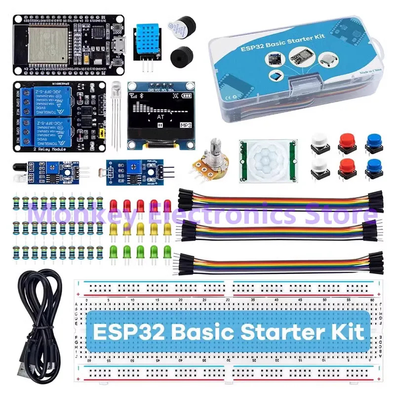
- Arduino Uno (Mega is also compatible, Nano and Mini are not recommended due to limited pins unless using a modified approach as demonstrated in a separate video.) (in video at 08:53)
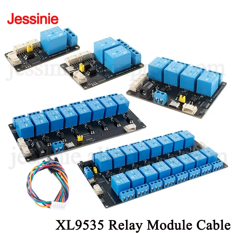
- 16-Channel Relay Module (in video at 00:04)
- External Power Supply (capable of handling at least 1.5A) (in video at 02:12)
- Connecting Wires
- Loads (e.g., lights, fans, etc.)
Wiring Guide
The 16-channel relay module requires an external power supply to drive the relays. Connect the positive and ground of the external power supply to the VCC and GND pins of the relay module, respectively (in video at 12:55). The module's ground pin must also be connected to the Arduino's GND. Each relay channel on the module corresponds to a pin, numbered 1 through 16. These pins should be connected to the Arduino's digital pins as defined in the code (pins 2 through 12 and A0 through A4). (in video at 09:03) If you wish to power the Arduino from the same external power supply, connect the positive terminal to the Arduino's VIN pin. (in video at 13:24)
Code Explanation
The provided Arduino code controls the 16-channel relay module. It defines the pins connected to the relay channels, the relay's trigger type (LOW in this case), and a loop delay. The core functionality lies in the channelControl() function, which allows you to turn a specific relay ON or OFF for a defined duration.
const int controlPin[16] = {2,3,4,5,6,7,8,9,10,11,12,A0,A1,A2,A3,A4}; // define pins

const int triggerType = LOW;// your relay type
Change triggerType to HIGH if your relay is high-triggered. (in video at 09:48)
void channelControl(int relayChannel, int action, int t)
{
  // ... (code omitted for brevity)
  digitalWrite(controlPin[relayChannel], state);
  // ...
}
To control a specific relay, call the channelControl() function with the relay channel (0-15), the desired action (1 for ON, 0 for OFF), and the duration in milliseconds. For instance, to turn relay 6 on for 2 seconds (in video at 11:53):
channelControl(6, 1, 2000); // turn relay 7 ON for 2 seconds
To control multiple relays simultaneously, use individual `digitalWrite` commands within the `loop()` function as shown below (in video at 09:03):
digitalWrite(controlPin[5], LOW); // relay 6 ON
digitalWrite(controlPin[2], LOW); // relay 3 ON
digitalWrite(controlPin[12], LOW); // relay 13 ON
Live Project/Demonstration
The demonstration (in video at 14:17) shows each relay activating sequentially. The serial monitor displays the status and activation time of each relay. You can modify the code to control specific relays based on your project requirements, such as turning on a heater when the temperature exceeds a certain threshold (in video at 16:24).
Video Chapters
- Introduction: 00:00
- Hardware Explained: 01:20
- How Much Load to Connect?: 05:37
- Relay Voltage Explained: 06:46
- Code Explained: 08:45
- Wiring Explained: 12:53
- Demonstration: 14:17
تصاویر
/*
 * Arduino code to control 16 channel relay with Arduino UNO
 *
 * Written by Ahmad Shamshiri for Robojax.com on Sunday, October 8, 2018
 * at 10:35 in Ajax, Ontario, Canada
 * Watch video instructions for this code: https://youtu.be/Q9aBI4ELKC4
 *
 * This code is "AS IS" without warranty or liability. Free to be used as long as you keep this note intact.
 * This code has been downloaded from Robojax.com
    This program is free software: you can redistribute it and/or modify
    it under the terms of the GNU General Public License as published by
    the Free Software Foundation, either version 3 of the License, or
    (at your option) any later version.

    This program is distributed in the hope that it will be useful,
    but WITHOUT ANY WARRANTY; without even the implied warranty of
    MERCHANTABILITY or FITNESS FOR A PARTICULAR PURPOSE.  See the
    GNU General Public License for more details.

    You should have received a copy of the GNU General Public License
    along with this program.  If not, see <https://www.gnu.org/licenses/>.
 */


const int controlPin[16] = {2,3,4,5,6,7,8,9,10,11,12,A0,A1,A2,A3,A4}; // define pins

const int triggerType = LOW;// your relay type
int loopDelay = 1000;// delay in loop
int tmpStat =1;


void setup() {
  for(int i=0; i<16; i++)
  {
    pinMode(controlPin[i], OUTPUT);// set pin as output
    if(triggerType ==LOW){
      digitalWrite(controlPin[i], HIGH); // set initial state OFF for low trigger relay
    }else{
       digitalWrite(controlPin[i], LOW); // set initial state OFF for high trigger relay
    }
  }

  Serial.begin(9600);// initialize serial monitor with 9600 baud
}

void loop() {

  for(int i=0; i<16; i++)
  {

   channelControl(i,tmpStat,200);// turn each relay ON for 200ms


  }
  if(tmpStat)
  {
    tmpStat=0;
  }else{
    tmpStat=1;
  }
 Serial.println("===============");
 //channelControl(6,1, 2000); // turn relay 7 ON for 2 seconds
 //channelControl(6,0, 5000); // turn relay 7 OFF for 5 seconds
 //channelControl(9,1, 3000); // turn relay 10 OFF for ever

 delay(loopDelay);// wait for loopDelay ms

}

/*
 * funciton: channelControl
 * turns ON or OFF specific relay channel
 * @param relayChannel is integer value channel from 0 to 15
 * @param action is 1 for ON or 0 for OFF
 * @param t is time in milliseconds
 */
void channelControl(int relayChannel, int action, int t)
{
  int state =LOW;
  String statTXT =" ON";
  if(triggerType == LOW)
  {
    if (action ==0)// if OFF requested
    {
      state = HIGH;
      statTXT = " OFF";
    }
    digitalWrite(controlPin[relayChannel], state);
    if(t >0 )
    {
      delay(t);
    }
       Serial.print ("Channel: ");
       Serial.print(relayChannel);
       Serial.print(statTXT);
       Serial.print(" - ");
       Serial.println(t);
  }else{
    if (action ==1)// if ON requested
    {
      state = HIGH;
    }else{
      statTXT = " OFF";
    }
    digitalWrite(controlPin[relayChannel], state);
    if(t >0 )
    {
      delay(t);
    }
       Serial.print ("Channel: ");
       Serial.print(relayChannel);
       Serial.print(statTXT);
       Serial.print(" - ");
       Serial.println(t);
  }

}/*
* Arduino code to control 16 channel relay with Arduino UNO
* Control more than 1 relay
* Written by Ahmad Shamshiri for Robojax.com on Sunday, October 8, 2018
* at 10:35 in Ajax, Ontario, Canada
* Watch video instructions for this code: https://youtu.be/Q9aBI4ELKC4
*
* This code is "AS IS" without warranty or liability. Free to be used as long as you keep this note intact.
* This code has been downloaded from Robojax.com
This program is free software: you can redistribute it and/or modify
it under the terms of the GNU General Public License as published by
the Free Software Foundation, either version 3 of the License, or
(at your option) any later version.
This program is distributed in the hope that it will be useful,
but WITHOUT ANY WARRANTY; without even the implied warranty of
MERCHANTABILITY or FITNESS FOR A PARTICULAR PURPOSE. See the
GNU General Public License for more details.
You should have received a copy of the GNU General Public License
along with this program. If not, see <https://www.gnu.org/licenses/>.
*/
const int controlPin[16] = {2,3,4,5,6,7,8,9,10,11,12,A0,A1,A2,A3,A4}; // define pins
const int triggerType = LOW;// your relay type
int loopDelay = 1000;// delay in loop
int tmpStat =1;
void setup() {
for(int i=0; i<16; i++)
{
pinMode(controlPin[i], OUTPUT);// set pin as output
if(triggerType ==LOW){
digitalWrite(controlPin[i], HIGH); // set initial state OFF for low trigger relay
}else{
digitalWrite(controlPin[i], LOW); // set initial state OFF for high trigger relay
}
}
Serial.begin(9600);// initialize serial monitor with 9600 baud
}
void loop() {
digitalWrite(controlPin[5], LOW); // relay 6 ON
digitalWrite(controlPin[2], LOW); // relay 3 ON
digitalWrite(controlPin[12], LOW); // relay 13 ON
digitalWrite(controlPin[5], HIGH); // relay 6 OFF
}مواردی که ممکن است به آنها نیاز داشته باشید
-
ایبی
-
علیاکسپرسماجیول ریلی 16 کاناله 5V، 12V یا 24V را از علیاکسپرس خریداری کنید.s.click.aliexpress.com
-
بنگ گودماجیول ریلی 16 کاناله را از بنگود خریداری کنیدbanggood.com
منابع و مراجع
-
خارجی
-
خارجیحل یک مشکل سیمکشی با این ماجیول (ویدیو یوتیوب)youtube.com
-
خارجیرگولاتور ولتاژ کاهنده LM2596ti.com
-
خارجیفتوسلر ۴ پینی DIPwebpagefx.com
-
خارجیماجیول ریلی 16 کاناله 5V، 12V یا 24V را از علیاکسپرس خریداری کنید.s.click.aliexpress.com
-
خارجی
-
خارجی
-
خارجیماجیول ریلی 16 کاناله را از بنگود خریداری کنیدbanggood.com
فایلها📁
هیچ فایلی موجود نیست.