Arduino ve L293D Kullanarak IR Uzaktan Kumanda ile DC Motor Kontrolü
Giriş
Bu eğitim, bir IR uzaktan kumanda, bir kızılötesi alıcı ve bir Arduino kartı kullanarak bir DC motorun yönünü ve durdurma işlevini nasıl kontrol edeceğinizi gösterir. L293D motor sürücü çipi, Arduino'nun düşük akımlı sinyallerinin motoru güvenli bir şekilde sürmesine izin veren aracı görevi görür. Bu proje, uzaktan kumandayı motor kontrolüyle birleştirmeye pratik bir giriş niteliğindedir ve çeşitli robotik ve otomasyon projeleri için olanaklar sunar.
Bu kurulumla neler yapabileceğinize dair birkaç pratik fikir:
- Küçük bir robotik arabanın veya gezginin hareketini kontrol etmek.
- Uzaktan kumandalı bir kamera kaydırıcısı veya eğim-döndürme mekanizması oluşturmak.
- Kendin yap bir fan veya başka bir küçük cihaz için kablosuz açma/kapama anahtarı oluşturmak.
- Bir model veya küçük proje için uzaktan kumandalı bir kapı veya kilit mekanizması geliştirmek.


Gerekli Donanım
- Arduino kartı (örn. Uno)
- L293D motor sürücü IC
- DC motor (küçük, 3-9V)
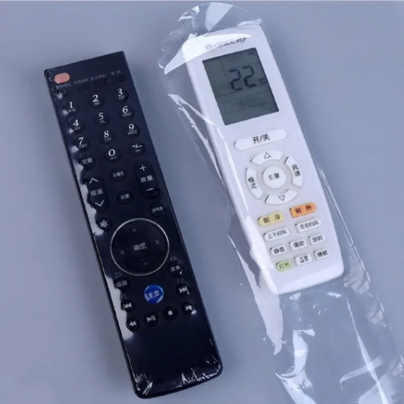
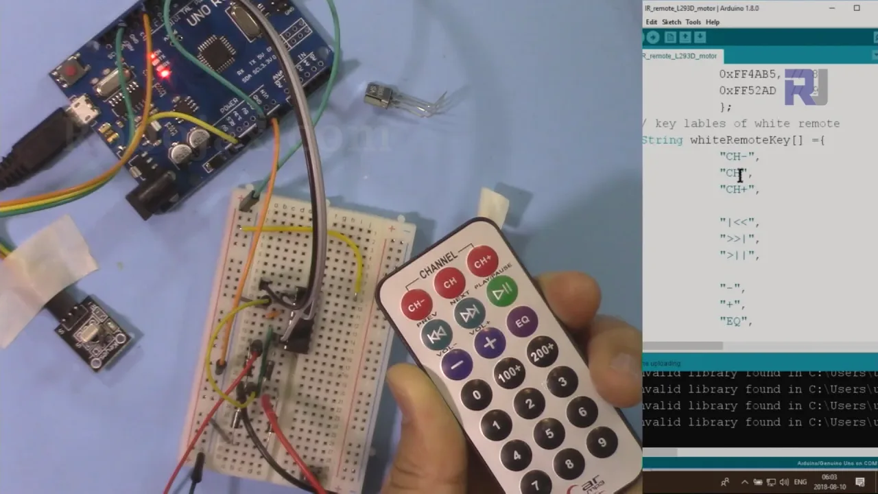
- IR uzaktan kumanda (siyah veya gümüş/beyaz)
- IR alıcı modülü (PCB'li veya PCB'siz)
- Motor için harici güç kaynağı (örn. 9V pil)
- Jumper kablolar ve breadboard
Bağlantı Rehberi
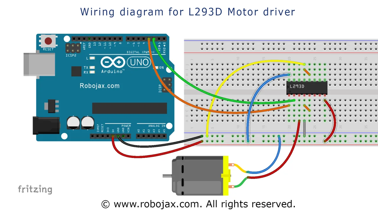
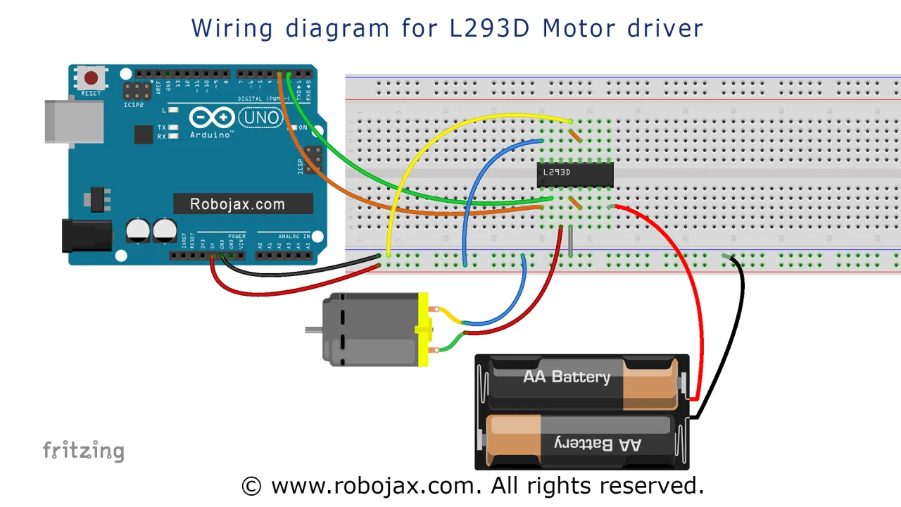
Bu proje için L293D çipi, Arduino'dan gelen sinyallere dayalı olarak motoru kontrol etmek için kullanılır. Bağlantılar şu şekildedir:
- Güç ve Toprak: L293D'nin 16. pini Arduino'nun 5V'una bağlanır. 4, 5, 12 ve 13 numaralı pinler birbirine ve ortak toprağa bağlanır. Harici motor güç kaynağı (örn. 9V), 8. pine (VCC2) bağlanır.
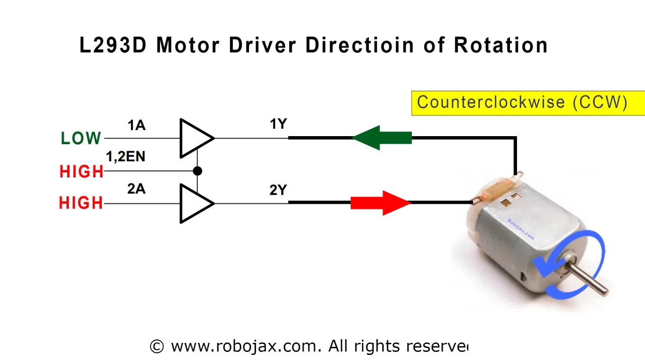
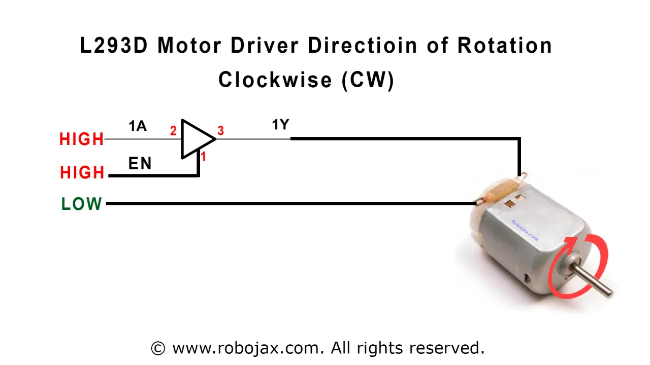
- Motor Bağlantıları: DC motorun iki teli L293D'nin 3 ve 6 numaralı pinlerine bağlanır. Gerekirse bu bağlantıları ters çevirerek dönüş yönü değiştirilebilir. Çip üzerindeki serbest geçiş diyotları, motorun ürettiği voltaj yükselmelerine karşı koruma sağlar.
- Kontrol Pinleri: 1. pin (Enable 1,2) Arduino pin 8'e bağlanır. 2. pin (Input 1A) Arduino pin 2'ye ve 7. pin (Input 2A) Arduino pin 7'ye bağlanır. Bu Arduino pinleri motorun yönünü ve hızını kontrol eder.
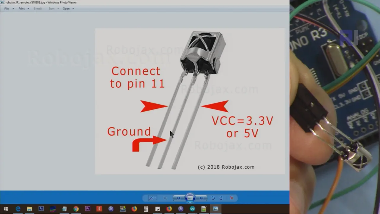
- IR Alıcı: IR alıcının sinyal pini Arduino pin 11'e bağlanır. VCC ve GND pinleri sırasıyla Arduino'nun 5V ve GND'sine bağlanır. Çıplak bir alıcı modülü kullanıyorsanız, pin düzeni VCC, GND ve sinyal çıkışıdır.
Ayrıntılı bir bağlantı şeması aşağıda verilmiştir.

Motorun güç kaynağı, Arduino'nun mantık kaynağından ayrıdır; bu, Arduino'nun voltaj regülatörünü aşırı yüklemeden motora yeterli akımı sağlamak için çok önemlidir.
Kod Açıklaması
Bu eğitim iki ayrı program içerir. Birincisi, IR uzaktan kumandayı L293D sürücüsüyle birleştiren ana proje kodudur. İkincisi, L293D motor sürücüsünü bağımsız olarak test etmek için daha basit bir programdır.
Arduino kullanarak bir servo motoru IR uzaktan kumandayla kontrol etme kaynağı
Bu, projenin tam programıdır. IR alıcı kitaplığını ve L293D motor kontrol mantığını entegre eder. Kod, belirli uzaktan kumandanız ve alıcı türünüz için kolayca yapılandırmanıza izin verecek şekilde yapılandırılmıştır.
Kullanıcı tarafından yapılandırılabilir bölüm kodun en üstündedir. Ayarlamanız gerekenler şunlardır:
İlk olarak, IR uzaktan kumanda türünüzü ve alıcı modülünüzü belirtmelisiniz. type değişkeni, siyah uzaktan kumanda için 'B' veya beyaz/gümüş uzaktan kumanda için 'W' olarak ayarlanmalıdır. Boolean değişkeni PCB, PCB'li bir alıcı modülü kullanıyorsanız 1 veya çıplak alıcı kullanıyorsanız 0 olarak ayarlanmalıdır.
const char type ='B';// W beyaz için, B siyah için. 'B' veya 'W' gibi tek tırnak işaretlerini koruyun
const boolean PCB = 0;// alıcı PCB ise 1, değilse 0 olarak ayarlayın. Ayrıntılar için videoya bakın
Ardından, uzaktan kumandanızda motoru kontrol edecek tuşları tanımlayabilirsiniz. RIGHT, LEFT ve STOP dizeleri, kullanmak istediğiniz tuşların etiketlerine ayarlanır. Örneğin, siyah uzaktan kumandayla varsayılan, sağ ok (>), sol ok (<) ve OK düğmesidir. Bunlar, blackRemoteKey[] gibi dizilerde tanımlanan tuş etiketleriyle eşleşmelidir.
const String RIGHT=">";// motoru uzaktan kumandadaki bu tuşla sağa (CW) hareket ettir
const String LEFT ="<";// motoru uzaktan kumandadaki bu tuşla sola (CCW) hareket ettir
const String STOP ="OK";// motoru uzaktan kumandadaki bu tuşla durdur
Ayrıca motor ve alıcı için kullanılan Arduino pinlerini de ayarlayabilirsiniz. Kod, L293D için P1A, P2A ve EN12 ile IR alıcı için RECV_PIN tanımlar. Farklı pinler kullanmak isterseniz, bu tanımları değiştirebilirsiniz.
#define P1A 2 // pin 2'yi P1A olarak tanımla
#define P2A 7 // pin 7'yi P2A olarak tanımla
#define EN12 8 // pin 8'i 1,2EN enable olarak tanımla
Ana mantık motorAction() fonksiyonu tarafından yönetilir. Bir tuşa basıldığında, robojaxValidateCode() fonksiyonu bunu çözer ve tuşun adıyla motorAction() fonksiyonunu çağırır. Bu fonksiyon, adı sizin RIGHT, LEFT ve STOP değişkenlerinizle karşılaştırır ve motoru doğru yönde döndürmek veya durdurmak için L293D() fonksiyonunu buna göre çağırır.
Arduino kullanarak basit bir L293 motor kontrolörü için kaynak
Bu, L293D çipi için temel bir test programıdır. IR uzaktan kumanda gerektirmez. Bunun yerine, kablolamanızın doğru olduğunu doğrulamak için motoru otomatik olarak bir dizi eylemden geçirir.
Bu taslakta kullanıcı tarafından yapılandırılabilir tek kısım, kablolamanızla eşleşmesi gereken pin tanımıdır:
#define P1A 2 // pin 2'yi P1A olarak tanımla
#define P2A 7 // pin 7'yi P2A olarak tanımla
#define EN12 8 // pin 8'i 1,2EN enable olarak tanımla
loop() içinde, kod L293D_con() fonksiyonunu farklı parametrelerle çağırır. İlk parametre bir karakterdir: bir yön için 'L' ve diğer yön için 'R'. İkinci parametre bir tamsayıdır: motoru çalıştırmak için 1 ve durdurmak için 0. Bu fonksiyon, motor sürücüsünü IR kontrol mantığıyla entegre etmeden önce test etmenin basit bir yoludur.
Canlı Proje Gösterimi
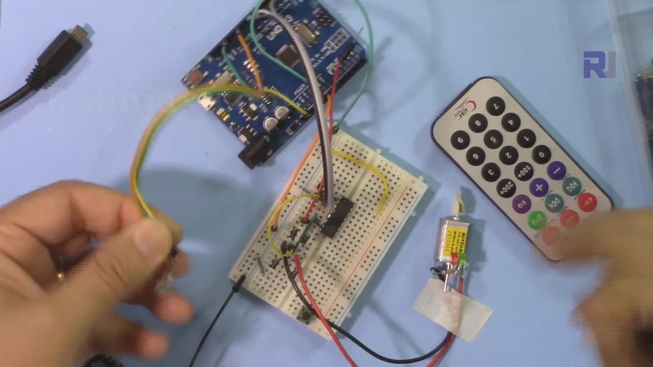
Videoda proje hem siyah hem de gümüş uzaktan kumandalarla gösterilmektedir. Sunucu önce PCB alıcı modüllü siyah uzaktan kumandayı kullanır. Kodu doğru ayarlarla (type='B', PCB=1) yükledikten sonra, sağ ok tuşuna basmak motorun bir yönde dönmesine, sol ok tuşu ters yönde dönmesine ve OK düğmesi durmasına neden olur.
Gösterim daha sonra gümüş uzaktan kumandaya geçer. Kod, kontrol için CH+ ve CH- gibi gümüş uzaktan kumandanın tuş etiketlerini kullanacak şekilde güncellenir. Sunucu, motorun bu farklı düğmelere doğru şekilde tepki verdiğini gösterir.
Son olarak sunucu PCB modülünü çıkarır ve çıplak IR alıcıyı kullanır. Kodda yapılması gereken tek değişiklik PCB=0 ayarlamaktır. Gösterim, motorun hâlâ başarıyla kontrol edildiğini doğrulayarak kodun her iki alıcı türünü de doğru şekilde işlediğini kanıtlar.
Bölümler
- [00:00] Giriş ve proje gösterimi
- [00:53] Ön koşullar ve önerilen videolar
- [02:14] L293D çipi kablolama açıklaması
- [07:30] Kod açıklaması ve yapılandırma
- [14:15] Siyah uzaktan kumanda ve PCB ile gösterim
- [16:04] Gümüş uzaktan kumanda ve PCB ile gösterim
- [17:42] PCB'siz gümüş uzaktan kumanda ile gösterim
- [18:23] PCB'siz siyah uzaktan kumanda ile gösterim
Görseller
/*
 * Original Infrared library from - http://arcfn.com
 *
 * This is Arduino code for the L293D DC motor driver.
 * It uses an IR remote control to rotate the DC motor clockwise (CW), counter-clockwise (CCW), and stop it.
 * Watch instructions for this video: https://youtu.be/e0pvfJbdw_o
 * To get the library and files related to this code, visit http://robojax.com/learn/arduino
 // Written for Robojax.com video

 * Code is available at http://robojax.com/learn/arduino

 *
 // Written by Ahmad S. for Robojax.com on
// August 10, 2018 at 22:03 in Ajax, Ontario, Canada
    This program is free software: you can redistribute it and/or modify
    it under the terms of the GNU General Public License as published by
    the Free Software Foundation, either version 3 of the License, or
    (at your option) any later version.

    This program is distributed in the hope that it will be useful,
    but WITHOUT ANY WARRANTY; without even the implied warranty of
    MERCHANTABILITY or FITNESS FOR A PARTICULAR PURPOSE.  See the
    GNU General Public License for more details.

    You should have received a copy of the GNU General Public License
    along with this program.  If not, see <https://www.gnu.org/licenses/>.
*/
// DC motor control
#define P1A 2 // define pin 2 as for P1A
#define P2A 7 // define pin 7 as for P2A
#define EN12 8 // define pin 8 as for 1,2EN enable

// remote settings start
#include <IRremote.h>

int RECV_PIN = 11;
const char type ='B';// W for white, B for black. Must keep single quotes like 'B' or 'W'
const boolean PCB = 0;// if receiver is PCB set to 1, if not set to 0. See video for details
boolean displayCode = false;// to display remote code. if not, set to false

// IR remote settings
const String RIGHT=">";// move motor to the right (CW) with this key on remote
const String LEFT ="<";// move motor to the left (CCW) with this key on remote
const String STOP ="OK";// stop motor with this key on remote
// remote settings end

IRrecv irrecv(RECV_PIN);

// this is array holding codes for White Remote when used with PCB version of receiver
unsigned int whiteRemotePCB[] ={
            0xE318261B, // CH-
            0x511DBB,   // CH
            0xEE886D7F,  // CH+

            0x52A3D41F, // |<<
            0xD7E84B1B, // >>|
            0x20FE4DBB, // >||

            0xF076C13B, // -
            0xA3C8EDDB, // +
            0x12CEA6E6, // EQ

            0xC101E57B, // 0
            0x97483BFB, // 100+
            0xF0C41643, // 200+

            0x9716BE3F, // 1
            0x3D9AE3F7, // 2
            0x6182021B, // 3

            0x8C22657B, // 4
            0x488F3CBB, // 5
            0x449E79F,  // 6

            0x32C6FDF7, // 7
            0x1BC0157B, // 8
            0x3EC3FC1B  // 9
            };

// this is array holding codes for White Remote when used with non-PCB version of receiver
unsigned int whiteRemote[] ={
            0xFFA25D, // CH-
            0xFF629D,   // CH
            0xFFE21D,  // CH+

            0xFF22DD, // |<<
            0xFF02FD, // >>|
            0xFFC23D, // >||

            0xFFE01F, // -
            0xFFA857, // +
            0xFF906F, // EQ

            0xFF6897, // 0
            0xFF9867, // 100+
            0xFFB04F, // 200+

            0xFF30CF, // 1
            0xFF18E7, // 2
            0xFF7A85, // 3

            0xFF10EF, // 4
            0xFF38C7, // 5
            0xFF5AA5,  // 6

            0xFF42BD, // 7
            0xFF4AB5, // 8
            0xFF52AD  // 9
            };
// key lables of white remote
 String whiteRemoteKey[] ={
            "CH-",
            "CH",
            "CH+",

            "|<<",
            ">>|",
            ">||",

            "-",
            "+",
            "EQ",

            "0",
            "100+",
            "200+",

            "1",
            "2",
            "3",

            "4",
            "5",
            "6",

            "7",
            "8",
            "9"
            };

// this is array holding codes for Black Remote when used with non-PCB version of receiver
 unsigned int blackRemote[] ={
            0xFF629D, // ^
            0xFF22DD,   // <
            0xFF02FD,  // OK
            0xFFC23D, // >
            0xFFA857, // v

            0xFF6897, // 1
            0xFF9867, // 2
            0xF0C41643, // 3

            0xFF30CF, // 4
            0xFF18E7, // 5
            0xFF7A85,  // 6

            0xFF10EF, // 7
            0xFF38C7, // 8
            0xFF5AA5,  // 9

            0xFF42BD, // *
            0xFF4AB5, // 0
            0xFF52AD  // #
            };

// this is array holding codes for Black Remote when used with PCB version of receiver
 unsigned int blackRemotePCB[] ={
            0x511DBB, // ^
            0x52A3D41F,   // <
            0xD7E84B1B,  // OK
            0x20FE4DBB, // >
            0xA3C8EDDB, // v


            0xC101E57B, // 1
            0x97483BFB, // 2
            0xF0C41643, // 3

            0x9716BE3F, // 4
            0x3D9AE3F7, // 5
            0x6182021B,  // 6

            0x8C22657B, // 7
            0x488F3CBB, // 8
            0x449E79F,  // 9

            0x32C6FDF7, // *
            0x1BC0157B, // 0
            0x3EC3FC1B  // #
            };

// Black remote key names
 String blackRemoteKey[] ={
            "^",
            "<",
            "OK",
            ">",
            "v",

            "1",
            "2",
            "3",

            "4",
            "5",
            "6",

            "7",
            "8",
            "9",

            "*",
            "0",
            "#"
            };

decode_results results;


/*
 * Permission granted to share this code given that this
 * note is kept with the code.
 * Disclaimer: this code is "AS IS" and for educational purposes only.
 *
 */

void setup() {
  // L293 Motor Control Code by Robojax.com 2018025
  Serial.begin(9600);// setup Serial Monitor to display information
  pinMode(P1A, OUTPUT);// define pin as OUTPUT for P1A
  pinMode(P2A, OUTPUT);// define pin as OUTPUT for P2A
  pinMode(EN12, OUTPUT);// define pin as OUTPUT for 1,2EN

  Serial.println("Robojax IR Decode");
  Serial.println("Motor Control with Remote");
  irrecv.enableIRIn(); // Start the receiver


  // L293 Motor Control Code by Robojax.com 20180810
}

void loop() {
  // L293d Motor Control Code with IR by Robojax.com 20180810

  if (irrecv.decode(&results)) {
    if(displayCode)Serial.println(results.value, HEX);
    robojaxValidateCode(results.value);// used the "robojaxValidateCode" bellow
    irrecv.resume(); // Receive the next value
  }
  delay(50);// 50 millisecond delay
  // L293d Motor Control Code with IR by Robojax.com 20180810
}//loop end


/*
 * function: robojaxValidateCode
 * validates the remote code and prints the correct key name
 * cd is the code passed from the loop
 * Written by A. S. for Robojax
 */
void robojaxValidateCode(int cd)
{

  // Robojax IR Remote decoder
  int found=0;

 if(type =='W' && !PCB)
 {
    // Robojax IR White Remote decoder
    // if type is set to 'W' (white remote) and PCB=0 then check White remote code
      for(int i=0; i< sizeof(whiteRemote)/sizeof(int); i++)
      {
        if(whiteRemote[i] ==cd)
        {

          Serial.print("Key pressed:");
          Serial.println(whiteRemoteKey[i]);
          motorAction(whiteRemoteKey[i]);// take action
          found=1;
        }// if matched
      }// for
 }else if(type =='W' && PCB){
    // Robojax IR White Remote decoder
    // if type is set to 'W' (white remote) and PCB=1 then check White remote code
      for(int i=0; i< sizeof(whiteRemotePCB)/sizeof(int); i++)
      {
        if(whiteRemotePCB[i] ==cd)
        {

          Serial.print("Key pressed:");
          Serial.println(whiteRemoteKey[i]);
          motorAction(whiteRemoteKey[i]);// take action
          found=1;
        }// if matched
      }// for
 }else if(type =='B' && PCB){
    // Robojax IR Black Remote decoder
       // if type is set to 'B' (black remote) and PCB=1 then check Black remote code
       for(int i=0; i< sizeof(blackRemotePCB)/sizeof(int); i++)
      {
        // Robojax IR black Remote decoder
        if(blackRemotePCB[i] ==cd)
        {

          Serial.print("Key pressed:");
          Serial.println(blackRemoteKey[i]);
         motorAction(blackRemoteKey[i]);// take action
          found=1;
        }// if matched
      }// for
 }else{

      // if type is set to 'B' (black remote) and PCB =0 then check Black remote code
       for(int i=0; i< sizeof(blackRemote)/sizeof(int); i++)
      {
        // Robojax IR black Remote decoder
        if(blackRemote[i] ==cd)
        {

          Serial.print("Key pressed:");
          Serial.println(blackRemoteKey[i]);
          motorAction(blackRemoteKey[i]);// take action

          found=1;
        }// if matched
      }// for
 }// else
  if(!found){
    if(cd !=0xFFFFFFFF)
      {
    Serial.println("Key unknown");
      }
  }// found
}// robojaxValidateCode end

/*
 *
 * motorAction()
 * receives string "value" as input and based on the settings,
 * turns motor CW, CCW or STOP
 */
void motorAction(String value)
{
  // Robojax IR motor control
   if(value == RIGHT)
   {
    L293D('R',1);// rotate motor to the right (CCW)
   }

   if(value == LEFT)
   {
    L293D('L',1);// rotate motor to the left (CW)
   }

   if(value == STOP)
   {
    L293D('R',0);// stop motor
   }
}//motorAction end


/*
 * L293D(char dir, int en)
 * dir is character either L for CW direction
 *  or R for CCW direction
 *  en is integer 1 to rotate, 0 for stop
 */
void L293D(char dir, int en)
{
  if(dir =='L')
  {
    if(en ==0){
       Serial.println("CW Motor Stopped");
    }else{
       Serial.println("Rotating CW");
    }
    digitalWrite(EN12 ,en);// Enable 1A and 2A
    digitalWrite(P1A,HIGH);// send + or HIGH signal to P1A
    digitalWrite(P2A,LOW);// send - or LOW signal to P2A

  }else{
    if(en ==0){
       Serial.println("CCW Motor Stopped");
    }else{
       Serial.println("Rotating CCW");
    }
    digitalWrite(EN12 ,en);// Disable 1A and 2A
    digitalWrite(P1A,LOW);// send + or HIGH signal to P1A
    digitalWrite(P2A,HIGH);// send - or LOW signal to P2A
  }
}//L293D end++
/*
* This is the Arduino code for L293d DC motor Driver
* watch LE18-D80NK video for details https://youtu.be/MrYsmAwzfrM
* Code is available at http://robojax.com/learn/arduino
*
* Written by Ahmad S. for Robojax.com on
* August 9, 2018 at 22:03 in Ajax, Ontario, Canada
*/
// DC motor 1 control
#define P1A 2 // define pin 2 as for P1A
#define P2A 7 // define pin 7 as for P2A
#define EN12 8 // define pin 8 as for 1,2EN enable
/*
* Permission granted to share this code given that this
* note is kept with the code.
* Disclaimer: this code is "AS IS" and for educational purposes only.
*
*/
void setup() {
// L293 Motor Control Code by Robojax.com 2018025
Serial.begin(9600);// setup Serial Monitor to display information
pinMode(P1A, OUTPUT);// define pin as OUTPUT for P1A
pinMode(P2A, OUTPUT);// define pin as OUTPUT for P2A
pinMode(EN12, OUTPUT);// define pin as OUTPUT for 1,2EN
// L293 Motor Control Code by Robojax.com 2018025
}
void loop() {
// L293 Motor Control Code by Robojax.com 2018025
L293D_con('L',1);
delay(4000);
L293D_con('L',0);
delay(2000);
L293D_con('R',1);
delay(4000);
L293D_con('R',0);
delay(2000);
Serial.println("=========== Loop done");
delay(500);
// L293 Motor Control Code by Robojax.com 2018025
}
void L293D_con(char dir, int en)
{
if(dir =='L')
{
if(en ==0){
Serial.println(" CW Motor Stopped");
}else{
Serial.println(" Rotating CW");
}
digitalWrite(EN12 ,en);// Enable 1A and 2A
digitalWrite(P1A,HIGH);// send + or HIGH signal to P1A
digitalWrite(P2A,LOW);// send - or LOW signal to P2A
}else{
if(en ==0){
Serial.println(" CCW Motor Stopped");
}else{
Serial.println(" Rotating CCW");
}
digitalWrite(EN12 ,en);// Disable 1A and 2A
digitalWrite(P1A,LOW);// send + or HIGH signal to P1A
digitalWrite(P2A,HIGH);// send - or LOW signal to P2A
}
}//L293D_con endKaynaklar ve referanslar
-
DışDownload Library for Arduino (GitHub)github.com
Dosyalar📁
Veri Sayfası (pdf)
-
Yedi segment LED ekranı Arduino ile nasıl kullanılır
robojax_L293D_motor_shield_manual.pdf0.16 MB -
L293d datasheet
L293d_datasheet.pdf0.34 MB