Using an HC-SR501 Motion Sensor with a Relay and Arduino Code
In this tutorial, we will explore how to use the HC-SR501 motion sensor in conjunction with a relay to control an AC bulb or another type of load using an Arduino. The HC-SR501 is an infrared motion sensor that can detect motion up to 7 meters away, making it ideal for various applications such as security alarms or automatic lighting systems. By utilizing this sensor and a relay, you can create a project that turns on a light when motion is detected.

We will provide a step-by-step guide on the hardware setup, wiring instructions, and the Arduino code needed to achieve this functionality. For a clearer understanding of the process, be sure to watch the associated video (in video at 00:00).
Hardware Explained
The primary components in this project include the HC-SR501 motion sensor, a relay module, and an Arduino board. The HC-SR501 sensor has three pins: VCC, GND, and OUT. The VCC pin connects to a power source (5V), the GND pin connects to ground, and the OUT pin sends a signal to the Arduino when motion is detected.
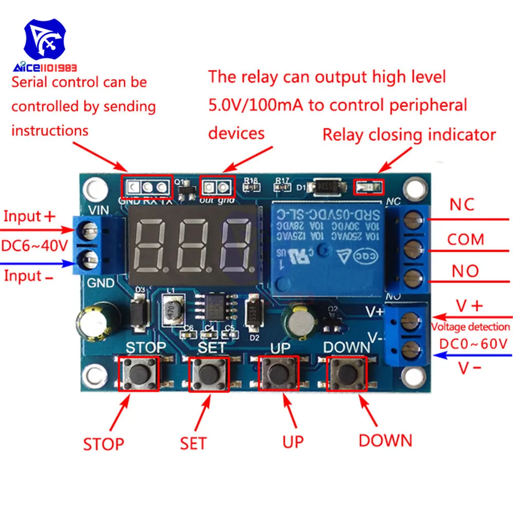
The relay module acts as a switch that can control high voltage devices. It has three main pins: COM (common), NO (normally open), and NC (normally closed). In this setup, we will use the NO pin, which connects to the load when the relay is activated. This allows the Arduino to control the relay based on the signal received from the motion sensor.
Datasheet Details
| Manufacturer | HC-SR501 |
|---|---|
| Part number | HC-SR501 |
| Logic/IO voltage | 5 V |
| Supply voltage | 5–20 V |
| Power consumption | 65 mA |
| Detection angle | 120 degrees |
| Detection distance | 3–7 m |
| Operating temperature | -15 to 70 °C |
| Output type | Digital |
| Package | Module |
- Ensure proper power supply (5–20 V) for the sensor.
- Adjust the sensitivity potentiometer for optimal detection range.
- Use the relay's NO pin to control the load effectively.
- Be cautious of the relay's current rating (10 A max).
- Test the motion sensor's detection range before final installation.
- Consider heat dissipation if using the relay for high loads.
Wiring Instructions

To wire the HC-SR501 motion sensor and relay with the Arduino, start by connecting the VCC pin of the motion sensor to the 5V pin on the Arduino. Next, connect the GND pin of the sensor to one of the GND pins on the Arduino. The OUT pin from the motion sensor should be connected to digital pin 2 on the Arduino.
For the relay module, connect the VCC pin to the 5V pin on the Arduino and the GND pin to the ground. The input pin (often labeled IN or similar) of the relay should be connected to digital pin 4 on the Arduino. Make sure to check the orientation of the relay to ensure it is set to normally open (NO) for this setup. Finally, connect the load (e.g., an AC bulb) to the relay according to the relay's specifications, ensuring the connections are secure.
Code Examples & Walkthrough
In the Arduino code, we define constants for the sensor and relay pins. The sensor pin is set to SENSOR_PIN, which is assigned to digital pin 2, and the relay pin is set to RELAY_PIN, assigned to digital pin 4. This configuration allows us to read the sensor's output and control the relay accordingly.
const int SENSOR_PIN = 2; // the Arduino pin connected to the output of the sensor
const int RELAY_PIN = 4; // the Arduino pin which is connected to control the relay
In the setup() function, we initialize the serial monitor for debugging and set the pin modes for the sensor and relay pins. This ensures the Arduino knows which pins are inputs and outputs.
void setup() {
  Serial.begin(9600); // setup Serial Monitor to display information
  pinMode(SENSOR_PIN, INPUT); // Define SENSOR_PIN as Input from sensor
  pinMode(RELAY_PIN, OUTPUT); // Define RELAY_PIN as OUTPUT for relay
}
In the loop() function, we continuously check the state of the motion sensor. If motion is detected, we print a message to the serial monitor and turn the relay on by setting it to low. If no motion is detected, we print a different message and turn the relay off by setting it to high.
void loop() {
  int motion = digitalRead(SENSOR_PIN); // read the sensor pin
  if (motion) {
    Serial.println("Motion detected");
    digitalWrite(RELAY_PIN, LOW); // Turn the relay ON
  } else {
    Serial.println("===Nothing moves");
    digitalWrite(RELAY_PIN, HIGH); // Turn the relay OFF
  }
  delay(500);
}
Demonstration / What to Expect
When the motion sensor detects movement, the relay will activate, allowing power to flow to the connected load, such as an AC bulb. You should see the bulb turn on immediately upon motion detection. If the sensor does not detect any movement, the bulb will remain off. Be aware that the sensitivity settings of the sensor will affect its detection range, so adjustments may be necessary for optimal performance (in video at 05:00).
Common pitfalls include incorrect wiring or exceeding the relay's current limits, which can lead to failure. Ensure all connections are secure and test the setup in a controlled environment before final use.
Video Timestamps
- 00:00 Start
- 00:35 Hardware explained
- 04:35 Relay power rating
- 06:00 Wiring explained
- 07:53 Arduino Code Explained
- 09:48 Demonstration of this project
Images

/*
 * This Arduino code uses an HS-SR501 motion sensor and a relay
 * and switches an alarm or a device using the relay when motion is detected.
 * The device can be an alarm, a light, or any other device.
 *

 * Written by Ahmad Shamshiri on August 5, 2018, at 12:36 PM for Robojax.com
 * in Ajax, Ontario, Canada
 * Watch the video instruction for this code: https://youtu.be/QQ7iDagQnQM
 * This code has been downloaded from Robojax.com

 */

const int SENSOR_PIN = 2;// the Arduino pin connected to the output (middle) wire of the sensor
const int RELAY_PIN = 4;// the Arduino pin which is connected to control the relay

void setup() {
  Serial.begin(9600);// setup Serial Monitor to display information
   Serial.println("Robojax Arduino Tutorial");
   Serial.println("HC-SR501 sensor with relay");
  pinMode(SENSOR_PIN, INPUT);// Define SENSOR_PIN as Input from sensor
  pinMode(RELAY_PIN, OUTPUT);// Define RELAY_PIN as OUTPUT for relay
}

void loop() {
  // Robojax.com HC-SR501 motion sensor tutorial August 5, 2018
  int motion =digitalRead(SENSOR_PIN);// read the sensor pin and stores it in "motion" variable

  // if motion is detected
  if(motion){
    Serial.println("Motion detected");
    digitalWrite(RELAY_PIN, LOW);// Turn the relay ON
  }else{
     Serial.println("===Nothing moves");
     digitalWrite(RELAY_PIN,HIGH);// Turn the relay OFF
  }
  delay(500);
  // Robojax.com HC-SR501 motion sensor tutorial August 5, 2018
}
Things you might need
-
Amazon
-
eBay
-
AliExpressPurchase HC-SR501 HC-SR505 HW-MS03 motion sensor from AliExpresss.click.aliexpress.com
Resources & references
No resources yet.
Files📁
No files available.