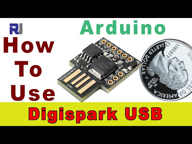
شروع به استفاده از برد آردوینو دیجیاسپارک USB ATtiny85
```html
استفاده از برد آردوینو Digispark USB ATtiny85 را شروع کنید
این راهنما مقدمهای جامع بر روی بورد توسعه USB ATtiny85 دیجیاسپارک ارائه میدهد، پلتفرمی جمع و جور و چندمنظوره که با آردوینو سازگار است. اندازه کوچک، مصرف پایین انرژی و سازگاری با IDE آردوینو، آن را برای طیف گستردهای از پروژهها ایدهآل میسازد.
در اینجا چند ایده پروژه برای شروع کار شما آورده شده است:
- نمایشگر LED پوشیدنی مینیاتوری
- یک ربات کوچک با کنترل از راه دور
- یک کیبورد یا ماوس USB جمع و جور
- یک گره حساس(حس کننده) کوچک و کممصرف
سختافزار/قطعات
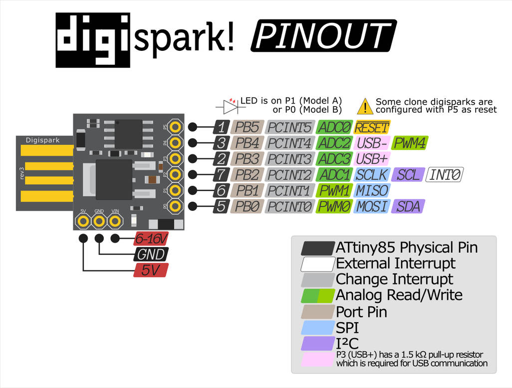
برد دیجیاسپارک دارای شش پایه ورودی/خروجی عمومی (GPIO) است، که شامل چهار ورودی آنالوگ و چندین پایه قادر به مدولاسیون عرض پالس (PWM) میباشد. همچنین یک LED قدرت داخلی و یک LED امتحان جداگانه به پایه ۱ متصل شده است. این برد از طریق USB یا منبع تغذیه خارجی تا ۱۶ ولت تغذیه میشود، که توسط یک رگولاتور ولتاژ داخلی به ۵ ولت کاهش مییابد. (در ویدئو در ۰۲:۱۱)
%%WIRING%%
راهنمای سیمکشی
دِیجیاسپارک با هدرهای پایه عرضه میشود که نیاز به لحیمکاری دارند. (در ویدیو در 01:22) قبل از لحیمکاری حتماً هدرها را به درستی همتراز کنید. پایه 1 بسیار حیاتی است زیرا LED آزمایشی روی بورد را کنترل میکند.
توضیحات شِفر (کود)
در حالی که هیچ قطعه کدی به وضوح ارائه نشده است، ویدیو یک طرح ساده چشمکزن را برای آزمایش عملکرد بورد نشان میدهد. عناصر کلیدی شِفر (کود) شامل:
pinMode(1, OUTPUT); // Sets pin 1 as an output to control the LED (in video at 11:55)
digitalWrite(1, HIGH); // Turns the LED ON (in video at 12:07)
delay(1000); // Keeps the LED ON for 1 second (1000 milliseconds) (in video at 12:13)
digitalWrite(1, LOW); // Turns the LED OFF (in video at 12:20)
delay(1000); // Keeps the LED OFF for 1 second
متن: LED_BUILTINثابت، که معمولاً در شِفر (کود) آردوینو استفاده میشود، باید با1به هدف قرار دادن LED آزمایشی Digispark.delay()توابع کنترل کننده نرخ چشمک زدن. (در ویدیو در ۱۰:۵۰)
پروژه زنده/مظاهره
این ویدئو بارگذاری اسکچ بلینک را به دیجیاسپارک نشان میدهد. نکته کلیدی که باید به آن توجه کنید، فرآیند بارگذاری است: پس از کامپایل، IDE آردوینو از شما میخواهد که دیجیاسپارک را وصل کنید. سپس شِفر (کود) را از طریق USB بارگذاری میکند. (در ویدئو در ۱۱:۲۴)
فصلها
- مقدمهای بر دیجیاسپارک
- [01:08] سختافزار توضیح داده شده
- مشخصات، دیاگرامها و برگه اطلاعات
- [08:46] راه اندازی آردوینو UNO
- [10:35] نمایش شِفر (کود) در حال اجرا با آردوینو
```
تصاویر


منابع و مراجع
-
خارجیاستفاده از یک LCD با دیجی اسپارکyoutu.be
فایلها📁
هیچ فایلی موجود نیست.