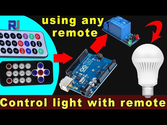
使用任意红外遥控器和Arduino及继电器控制交流灯泡
在本教程中,我们将学习如何使用红外遥控器通过Arduino和继电器模块来操作交流灯泡。该项目涉及解码遥控器的信号,并利用这些信号控制继电器,从而开启和关闭交流灯泡。在本教程结束时,您将能够使用任何红外遥控器来控制您的灯具。
我们将使用红外接收器捕捉遥控器发出的信号,Arduino 将解读这些信号以执行特定操作。提供的代码将允许您选择遥控器的类型(黑色或白色)以及您是使用 PCB 还是裸模块作为接收器。请确保观看相关视频以获取更多细节和说明(在视频中为 :00)。
硬件解析
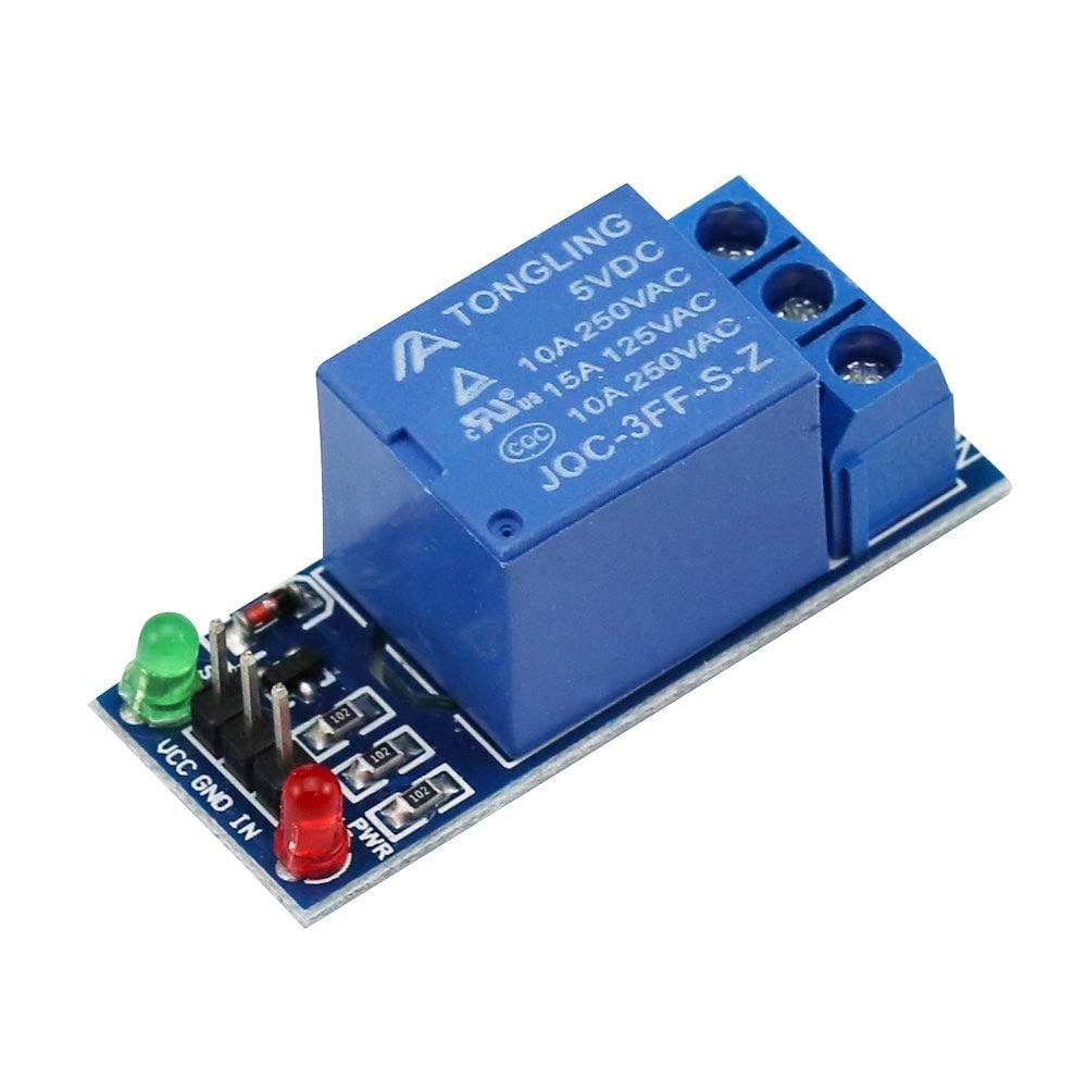
对于这个项目,主要组成部分包括Arduino主板、红外接收模块和继电器模块。红外接收器负责捕获来自遥控器的信号并将其发送到Arduino。继电器模块作为开关来控制交流灯泡,根据接收到的信号实现开关操作。

红外接收器通常在38 kHz的频率下工作,可以从约10到15米的距离检测信号。一旦Arduino接收到信号,它会对其进行解码,并使用继电器控制灯泡的电源。
接线说明

开始接线,将红外接收模块连接到Arduino。接收器的VCC引脚连接到Arduino的5V引脚,接地引脚连接到GND引脚。红外接收器的信号引脚应连接到数字引脚。11在 Arduino 上。
接下来,连接继电器模块。继电器的控制脚应连接到数字脚2在Arduino上。同时,将继电器的VCC和GND引脚分别连接到Arduino的5V和GND。最后,根据继电器的规格将AC灯泡接到继电器上,以确保安全操作。
代码示例与教程
在程序的设置阶段,我们初始化串行通信并设置继电器引脚。标识符RECV_PIN设置为11这就是红外接收器的信号针连接的地方。这使我们能够接收来自遥控器的数据。
void setup() {
  Serial.begin(9600);
  irrecv.enableIRIn(); // Start the receiver
  pinMode(RELAY_PIN, OUTPUT); // define a pin for relay as OUTPUT
  digitalWrite(RELAY_PIN, HIGH); // set relay to OFF at the beginning
}
在循环函数中,我们不断检查来自遥控器的信号。当检测到信号时,值被解码,并根据按下的键采取相应的行动。
void loop() {
  if (irrecv.decode(&results)) {
    Serial.println(results.value, HEX); // Print the received value
    robojaxValidateCode(results.value); // Validate the code
    irrecv.resume(); // Receive the next value
  }
  delay(100);
}翻robojaxValidateCode该函数将接收到的代码与遥控器的已知值进行检查。根据按下的按键,它将使用继电器执行相应的操作。
void robojaxValidateCode(int cd) {
  if (type == 'W' && !PCB) {
    // Check White remote codes
    for (int i = 0; i < sizeof(whiteRemote) / sizeof(int); i++) {
      if (whiteRemote[i] == cd) {
        Serial.print("Key pressed: ");
        Serial.println(whiteRemoteKey[i]);
        relayAction(whiteRemoteKey[i]); // Take action
      }
    }
  }
}在这个函数中,代码检查按下的键是否对应于定义的数组值。如果找到匹配,它将调用relayAction根据按下的键将继电器打开或关闭的功能。
演示 / 期待什么
完成布线并上传代码后,您可以使用红外遥控器控制 AC 灯泡。按下遥控器上的指定键,继电器应相应地激活或停用灯泡。确保测试每个按键以查看其响应(视频时长 5:00)。
视频时间戳
- 00:00 开始
- 00:49 介绍
- 02:00 接线和连接
- 05:27 Arduino 代码讲解
- 09:51 使用不同遥控器控制交流灯泡的演示
- 使用您的电视遥控器控制空调灯泡
图像

This code has not been parsed yet. Please return to the admin panel to parse it.|||您可能需要的东西
-
亚马逊从亚马逊购买红外遥控器amzn.to
-
易趣从eBay购买红外遥控器ebay.us
资源与参考
尚无可用资源。
文件📁
没有可用的文件。