This tutorial is part of: SunFounder Rasberry Pi Pico Pico 4WD Smart Car Kit
Files related to this group will be displayed together. Links to other videos are below this article.
Lesson 7 of 10: Line Tracking, Cliff Detection Calibrate Greyscale Sensor Raspberry Pi Pico Car
In this lesson from the Raspberry Pi Pico Smart Car course, we explore the fascinating world of autonomous navigation by combining a servo motor, an ultrasonic sensor, and motor control to enable the car to detect and avoid obstacles. This project transforms a basic four-wheel drive kit into an intelligent robot that can navigate dynamic environments, making it an excellent foundation for learning about sensor fusion and reactive control algorithms. The real-world value of this project extends far beyond the classroom, offering a platform for practical applications such as building a robotic vacuum that navigates around furniture, creating a security patrol robot that maps safe zones, or developing a prototype for an autonomous delivery vehicle that can navigate through crowded spaces.
The core of this project lies in using a servo motor to rotate an ultrasonic sensor, creating a simple radar system. By scanning the environment from 0 to 180 degrees, the car can measure distances to obstacles and identify the clearest path forward. This lesson provides a step-by-step guide on implementing the logic that interprets this sensor data to make intelligent driving decisions.
Hardware/Components
This project is based on the SunFounder Raspberry Pi Pico four-wheel drive car kit. While the exact model may vary, the core components required are:
- Raspberry Pi Pico microcontroller board
- SunFounder 4WD Smart Car chassis kit (or similar)
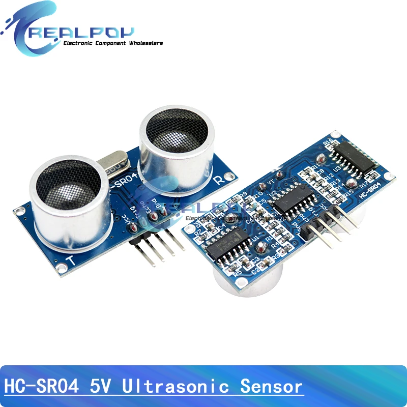
- Ultrasonic distance sensor (e.g., HC-SR04)
- Servo motor (for rotating the ultrasonic sensor)
- Motor driver board (integrated into the car kit)
- Power supply (batteries)
Wiring Guide
The wiring for this project is typically pre-configured on the SunFounder car kit's expansion board. The ultrasonic sensor's trigger and echo pins, along with the servo motor's signal pin, are connected to specific GPIO pins on the Raspberry Pi Pico. The motor driver is also connected to the Pico to control the direction and speed of the four motors.
For a detailed wiring diagram specific to your kit, please refer to the documentation provided by SunFounder. A general schematic is often included in the kit's manual or on the manufacturer's website.
Code Explanation
This lesson focuses on the logic and user-configurable parameters within the obstacle avoidance program. The code is structured to control the car's behavior based on input from the ultrasonic sensor. The key variables you can adjust to fine-tune the car's performance are typically defined at the top of the script.
Here are the primary user-configurable settings you will find in the code:
- Radar Reference Distance: This is the threshold distance (e.g., 20 cm) that determines if an obstacle is considered a "danger." If the sensor reads a distance less than this value, the car will initiate an avoidance maneuver.
- Step Angle: This is the increment (e.g., 10 degrees) by which the servo motor rotates when scanning the environment. A smaller step angle provides a more detailed scan but takes longer.
- Forward Speed: This variable (e.g., 30) sets the power level for the motors when the car is moving forward.
- Turning Speed: This variable (e.g., 50) sets the power level for the motors when the car is turning, which is typically higher than the forward speed to ensure a decisive turn.
- Forward Scan Angle: This value (e.g., 50 degrees) sets the range of angles the servo will scan when the car is moving forward. A narrower scan is faster and sufficient for detecting obstacles directly in the path.
To understand how to use these variables, imagine you want the car to be more cautious. You could increase the RADAR_REFERENCE to 25 cm, causing it to detect and avoid obstacles from a greater distance. Conversely, for a faster, more aggressive car, you could decrease this value to 15 cm.
The main logic uses a get_direction() function to analyze the sensor data. This function converts the array of distance readings into a string of '1's (empty space) and '0's (obstacle). It then splits this string at the zeros to find the widest continuous path. Based on the position of this widest path, the function returns a direction: 'left', 'right', or 'forward'. The main loop then executes the corresponding maneuver.
Live Project/Demonstration
(in video at 02:47) The instructor begins by demonstrating the obstacle avoidance feature. The car uses the servo to rotate the ultrasonic sensor, acting as a radar. As the car moves, it scans its surroundings to find an empty path.
(in video at 03:34) The code is run, and the car is tested in an open area. The instructor explains the code structure, showing how the get_distance() function from the sonar module is used to measure distances. The sensor's readings are displayed on the shell, demonstrating its accuracy and limitations.
(in video at 07:45) The instructor then opens the "obstacle_avoid" example and walks through its flowchart. This visual aid explains the decision-making process: the car scans, checks for danger, and if a path is blocked, it determines the best direction to turn based on the widest open path.
(in video at 16:02) A live test is performed. The car successfully detects an obstacle (a box) and maneuvers around it, turning left to find a clear path. The instructor explains the real-time data being printed to the shell, showing '0' for obstacle and '1' for clear space.
(in video at 22:53) A final, more complex demonstration is set up with multiple obstacles. The car navigates the course, making decisions to turn left or right to avoid collisions and find a clear route, showcasing the effectiveness of the algorithm in a more challenging environment.
Chapters
- [00:00] Introduction to the Lesson
- [01:31] Course and Kit Overview
- [02:47] Obstacle Avoidance Feature Demonstration
- [03:34] Testing the Ultrasonic Sensor
- [07:45] Understanding the Obstacle Avoidance Algorithm
- [12:49] Code Walkthrough: Main Loop and Logic
- [16:02] Live Testing and Data Analysis
- [22:53] Complex Obstacle Course Demonstration
This tutorial is part of: SunFounder Rasberry Pi Pico Pico 4WD Smart Car Kit
- Course Lesson 1 of 10: Raspberry Pi Pico 4WD Smart Car Kit from SunFounder by Robojax
- Course Lesson 2 of 10: Basic Python to drive Raspberry Pi Pico 4WD Smart Car Kit
- Course Lesson 3 of 10: Assembling Raspberry Pi Pico 4WD Smart Car Kit from SunFounder by Robojax
- Course Lesson 4 of 10: Raspberry Pi Pico Expansion board for 4WD Smart Car Kit
- Course Lesson 5 of 10: Controlling RGB LED WS2812B Using Raspberry Pi Pico
- Course Lesson 6 of 10: Controlling DC Motors using Raspberry Pi Pico 4WD Smart Car Kit
- Course Lesson 8 of 10: Raspberry Pi Pico Smart Car – Lesson 8: Servo Motor and Object Following
- Course Lesson 9 of 10: Obstacle Avoidance using Raspberry Pi Pico 4WD Smart Car
- Course Lesson 10 of 10: Controlling Raspberry Pi Pico 4WD Smart Car Kit with mobile App
Common Course Links
- Purchase SunFounder Pico 4WD Smart Car Kit from AliExpress
- Purchase SunFounder Pico 4WD Smart Car Kit from eBay
- Amazon Canada: Purchase Pico 4WD Smart Car Kit by SunFounder
- Amazon France: Purchase Pico 4WD Smart Car Kit by SunFounder
- Amazon Germany: Purchase Pico 4WD Smart Car Kit by SunFounder
- Amazon Italy: Purchase Pico 4WD Smart Car Kit by SunFounder
- Amazon Japan: Purchase Pico 4WD Smart Car Kit by SunFounder
- Amazon Spain: Purchase Pico 4WD Smart Car Kit by SunFounder
- Amazon UK: Purchase Pico 4WD Smart Car Kit by SunFounder
- Amazon USA: Purchase Pico 4WD Smart Car Kit buy SunFounder
- Purchase Pico 4WD Smart Car Kit from SunFounder.com
- SunFounder Pico-4wd Car Kit Documentation
- Video Play List of 10 lesson on SunFounder Pico 4WD Smart Car Kit
Resources & references
No resources yet.
Files📁
No files available.