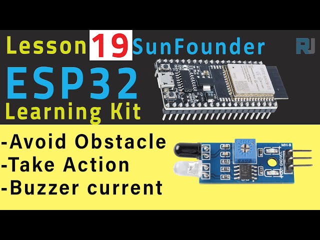
In this tutorial, we will learn how to use an infrared obstacle avoidance sensor with the ESP32 module to detect obstacles. This project will demonstrate how the sensor can trigger a buzzer when an obstacle is detected. The setup will also display the detection status on the serial monitor, providing a clear and interactive way to observe the sensor's functionality.
We will be working with the SunFounder ESP32 IoT Learning Kit, which includes the ESP32 microcontroller equipped with Wi-Fi and Bluetooth capabilities. The infrared sensor works by sending out infrared light, which will reflect off nearby obstacles. When the light is reflected back, the sensor will trigger an output signal that we will read in our code. We will also include a buzzer that activates when an obstacle is detected, providing an audible alert.
Hardware Explained
The main components of this project include the ESP32 module, the infrared obstacle avoidance sensor, and a buzzer. The ESP32 module serves as the central processing unit, handling sensor inputs and controlling outputs. It can be powered using a lithium battery, making it portable and flexible for various applications.
The infrared obstacle avoidance sensor consists of a transmitter and a receiver. The transmitter emits infrared light, while the receiver detects the reflected light from nearby objects. When an obstacle is present, the sensor's output pin goes low, signaling the ESP32 to take action, such as turning on the buzzer.
Datasheet Details
Manufacturer
SunFounder
Part number
Infrared Obstacle Avoidance Sensor
Operating Voltage
3.3 V - 5 V
Output Type
Digital (Low when obstacle detected)
Detection Range
Up to 20 cm
Response Time
Less than 10 ms
Package
Module
Power supply: 3.3 V to 5 V for operation.
Output signal goes low when an obstacle is detected.
Adjustable sensitivity via potentiometer.
Typical detection range is up to 20 cm.
Fast response time of under 10 ms.
Wiring Instructions
ESP32-19-obstacle_voide-wiring
To wire the infrared obstacle avoidance sensor to the ESP32, start by connecting the VCC pin of the sensor to the 5V pin on the ESP32. Next, connect the GND pin of the sensor to one of the GND pins on the ESP32. Finally, connect the OUT pin of the sensor to GPIO pin 14 on the ESP32.
For the buzzer, connect the negative terminal to GND and the positive terminal to GPIO pin 27. Ensure all connections are secure and that the sensor is powered correctly. The wiring should be straightforward, as the sensor and buzzer only require simple power and signal connections.
Code Examples & Walkthrough
In the code, we first define the pin connected to the obstacle avoidance sensor. This is done using the identifier avoidPin set to 14. We also declare a variable avoidState to hold the sensor's output state.
const int avoidPin = 14;  // the number of the avoid module pin

int avoidState = 0;
In the setup function, we initialize the serial communication and set the avoidPin as an input. This allows the ESP32 to read the sensor's output state.
Within the loop function, we continuously read the sensor's output using digitalRead(avoidPin) and store the result in avoidState. This value is then printed to the serial monitor, allowing us to see when an obstacle is detected (output will be 0) or not (output will be 1).
For the full code, please refer to the loading section below the article.
Demonstration / What to Expect
When the setup is complete and the code is uploaded, you should see the serial monitor displaying either a 0 or a 1 depending on whether an obstacle is detected. When an obstacle is within the detection range, the output will read 0, and the buzzer will sound. If the obstacle is removed, the output will read 1, and the buzzer will stop. This functionality is demonstrated in the video (in video at 12:30).
Common issues might include incorrect wiring, which could lead to the sensor not functioning properly, or mismatched baud rates in the serial monitor, preventing data from displaying accurately. Make sure to check these aspects if you encounter problems.
Video Timestamps
00:00 Start
1:57 Project introduction
4:33 Wiring Obstacle Avoidance
5:55 Arduino Code for Obstacle Avoidance
7:36 Selecting ESP32 Board and COM port on Arduino IDE