ESP32 Tutorial 13/55 - Arduino Beep with Active Buzzer | SunFounder's ESP32 IoT Learning kit
In this tutorial, we'll learn how to control an active buzzer using an ESP32 microcontroller and a transistor. The project involves turning the buzzer on and off, creating a beeping sound. With the ESP32's built-in Wi-Fi and Bluetooth capabilities, you can expand this project into more complex IoT applications in the future.

The components we'll use include the ESP32 board, an active buzzer, a transistor (S8050), and a resistor. By wiring these components correctly, we can control the buzzer's sound through the ESP32. Additionally, we will provide a brief overview of the wiring and code necessary to get this project up and running. For further clarification, be sure to check the video accompanying this tutorial (in video at 00:00).
Hardware Explained
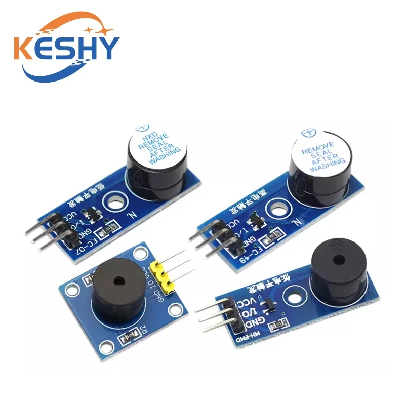
The main components of this project include the ESP32 microcontroller, the active buzzer, and the S8050 transistor. The ESP32 is a powerful microcontroller featuring both Wi-Fi and Bluetooth, allowing for a wide range of IoT projects. The active buzzer generates sound when a voltage is applied, while the S8050 transistor acts as a switch to control the buzzer with a low voltage signal from the ESP32.
The transistor has three pins: collector, base, and emitter. When a voltage is applied to the base pin through a resistor, it allows current to flow from the collector to the emitter, thus powering the buzzer. This setup ensures that we can control the buzzer safely without overloading the ESP32's GPIO pins.

Datasheet Details
| Manufacturer | SunFounder |
|---|---|
| Part number | TMBB 12 A05 |
| Operating voltage | 3–8 V |
| Rated voltage | 5 V |
| Maximum current | 30 mA |
| Oscillating frequency | 2700 ± 300 Hz |
- Use a 1 kΩ resistor to limit current to the transistor's base.
- Ensure the active buzzer is connected correctly with positive and negative terminals.
- Double-check the pin connections to prevent short circuits.
- Use a breadboard for easier connections and adjustments.
- The buzzer can operate at both 3.3V and 5V, but power it according to your circuit needs.
Wiring Instructions

To wire the components, start by inserting the active buzzer into the breadboard. Connect the positive terminal of the buzzer to the 3.3V pin on the ESP32. The negative terminal of the buzzer should be connected to the collector pin of the S8050 transistor. Next, insert the S8050 transistor into the breadboard, ensuring that the flat side is facing you. The left pin (collector) connects to the negative terminal of the buzzer, the middle pin (base) connects to a 1 kΩ resistor, and the right pin (emitter) connects to the ground.
Now, take the other end of the 1 kΩ resistor and connect it to GPIO pin 14 on the ESP32. Finally, connect the emitter pin of the transistor to the ground rail on the breadboard. Ensure that all connections are secure and double-check the alignment of the pins before powering the circuit.
Code Examples & Walkthrough
Here’s a brief overview of the code that controls the buzzer. First, we define the pin connected to the buzzer:
const int buzzerPin = 14; // the buzzer pinThis line sets up the variable buzzerPin to refer to pin 14 on the ESP32, which is used to control the buzzer.
Next, we set the buzzer pin as an output in the setup() function:
void setup()
{
  pinMode(buzzerPin, OUTPUT); // Set as output
}
This ensures that the ESP32 knows to use pin 14 to send signals to turn the buzzer on and off.
In the loop() function, we create a for loop to activate the buzzer multiple times:
for (int i = 0; i < 50; i++) // Loop 50 times and play a short tone each time
{
  digitalWrite(buzzerPin, HIGH); // Set to HIGH to make the buzzer sound
  delay(3); // Wait for 3 milliseconds
  digitalWrite(buzzerPin, LOW); // LOW to turn off the buzzer
  delay(3); //
}
This loop will make the buzzer beep 50 times, with each beep lasting for 3 milliseconds. After completing the loop, there is a 1-second delay before repeating.
Demonstration / What to Expect
When the wiring and code are set up correctly, powering the ESP32 should activate the buzzer, producing a series of beeps. If the buzzer does not sound, check the connections, especially the orientation of the transistor and the resistor. Ensure that the correct GPIO pin is being used in the code and that the power supply is adequate (in video at 01:30).
Video Timestamps
- 00:00 Start
- 1:45 Buzzer program introduction
- 5:57 Wiring buzzer and S8050 Transistor
- 9:57 Arduino Code for ESP32 Buzzer
- 12:52 Selecting ESP32 board and COM port
- 14:05 3.1 Buzzer project demonstration
Images

const int buzzerPin = 14; // the buzzer pin

void setup()
{
  pinMode(buzzerPin, OUTPUT); // Set as output
}

void loop()
{
  for (int i = 0; i < 50; i++) // Loop 50 times and play a short tone each time
  {
    digitalWrite(buzzerPin, HIGH); // Set to HIGH to make the buzzer sound
    delay(3); // Wait for 3 milliseconds
    digitalWrite(buzzerPin, LOW); // LOW to turn off the buzzer
    delay(3); //
  }
  delay(1000); // Wait for 1s before starting the next loop
}
Common Course Links
Common Course Files
Resources & references
-
DocumentationESP32 Tutorial 13/55- SunFounder Resouce page for Buzzerdocs.sunfounder.com
Files📁
Datasheet (pdf)
-
Buzzer MB12A05 C96093 datasheet
Buzzer_MB12A05_C96093_datasheet.pdf0.97 MB -
NPN Epitaxial Silicon Transistor SS8050 datasheet
SS8050-datasheet.pdf0.19 MB