ESP32 Tutorial 29/55 - Reading IR remote key press with ESP32| SunFounder's ESP32 IoT Learning kit
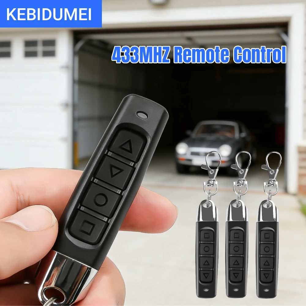
In this tutorial, we will learn how to detect infrared (IR) signals using the ESP32 module and a compatible IR receiver. When we press a button on the remote, the ESP32 will recognize the signal and execute specific actions, such as sounding a buzzer for particular key presses. This project is ideal for those looking to integrate remote control capabilities into their ESP32 applications (in video at 02:15).

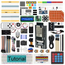
The ESP32 is a powerful microcontroller that combines Wi-Fi and Bluetooth capabilities, making it suitable for a wide range of IoT applications. In this project, we will use an IR receiver to interpret signals from a remote control. The key presses will be processed in the code, allowing us to take actions based on the received commands.
Hardware Explained
The main components for this project include the ESP32 microcontroller, an IR receiver module, and a buzzer. The ESP32 serves as the brain of the operation, processing the signals received from the IR receiver. The IR receiver detects the infrared signals from the remote control and converts them into electrical signals that the ESP32 can understand.
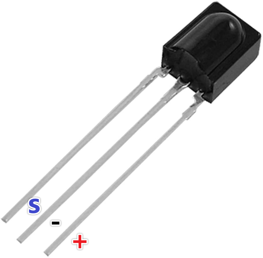
The IR receiver typically has three pins: VCC (power), GND (ground), and OUT (signal). The VCC pin is connected to a power source (3.3V or 5V), while the GND connects to the ground. The OUT pin sends the decoded signal to the ESP32, which can then be used to trigger various actions, such as activating a buzzer when a specific key is pressed.
Datasheet Details
| Manufacturer | Sharp |
|---|---|
| Part number | GP1UXC41 |
| Logic/IO voltage | 3.3 - 5.0 V |
| Supply voltage | 3.3 V (typ.) |
| Output current (per channel) | 20 mA (max) |
| Peak current (per channel) | 50 mA (max) |
| PWM frequency guidance | 38 kHz |
| Input logic thresholds | 0.3 Vcc (high), 0.2 Vcc (low) |
| Voltage drop / RDS(on) / saturation | 0.5 V (max) |
| Thermal limits | 85 °C (max) |
| Package | TO-92 |
| Notes / variants | Available in multiple configurations |
- Ensure correct power supply to avoid damage.
- Use short wires to minimize signal interference.
- Check the orientation of the IR receiver before connecting.
- Confirm that the remote control battery is functional.
- Use pull-up resistors if necessary for stability.
Wiring Instructions

To wire the IR receiver to the ESP32, start by identifying the three pins on the IR receiver: VCC, GND, and OUT. Connect the VCC pin to a 3.3V power source on the ESP32. Next, connect the GND pin to one of the ground (GND) pins on the ESP32. Finally, connect the OUT pin to GPIO pin 14 on the ESP32, which is designated for the IR receiver in the code.

Once the connections are made, ensure that the wiring is secure. If you are using a breadboard, insert the IR receiver such that the flat side is facing you and the bump is on the opposite side. This orientation will help you correctly identify the pins. Make sure to verify the connections before powering up the ESP32.
Code Examples & Walkthrough

install the IRremoteESP8266library by David Conran, Sebastien.
In the code, we define the IR receiver pin using the constant IR_RECEIVE_PIN, which is set to 14. We also create an instance of IRrecv to handle the IR signals.
const uint16_t IR_RECEIVE_PIN = 14;
IRrecv irrecv(IR_RECEIVE_PIN);
decode_results results;
This setup allows us to receive signals from the IR remote. In the setup() function, we initialize the serial communication and enable the IR receiver.
void setup() {
  Serial.begin(115200);
  irrecv.enableIRIn();
}
Within the loop() function, we check if an IR signal has been received. If so, we decode the key value and print it to the serial monitor.
if (irrecv.decode(&results)) {
    String key = decodeKeyValue(results.value);
    Serial.println(key);
    irrecv.resume();
}
This code snippet shows how we decode the received signal and print the corresponding key value to the serial monitor. The decodeKeyValue() function maps the received signal to specific button values, such as "0", "1", "EQ", and others. You can find the complete code loaded below the article.
Demonstration / What to Expect
Once the wiring is complete and the code is uploaded, pressing a button on the remote should display the corresponding key value on the serial monitor. For example, pressing the "2" button will print "2" to the monitor. If the key is not recognized, it will return "ERROR". The buzzer will sound when the designated key (e.g., "EQ") is pressed, providing immediate feedback.
Be cautious of common pitfalls, such as reversed polarity in your connections or using incorrect voltage levels. Ensure that the remote control works properly and has a functioning battery before testing your setup (in video at 15:30).
Video Timestamps
- 00:00 Start
- 2:05 Introduction to IR receiver
- 4:24 Wiring explained
- 6:08 Arduino code for IR receiver explained
- 10:06 Selecting ESP32 board and COM port in Arduino IDE
- 11:48 Project Demonstration
- 13:09 Active buzzer directly connected to ESP32
- 14:40 taking action when a key is pressed
- 15:30 Arduino code for taking action
- 16:54 Key press and buzzer demo
图像
#include <IRremoteESP8266.h>
#include <IRrecv.h>

 // 定义红外接收器引脚
const uint16_t IR_RECEIVE_PIN = 14;

 // 创建一个 IRrecv 对象
IRrecv irrecv(IR_RECEIVE_PIN);

 // 创建一个 decode_results 对象
decode_results results;

void setup() {
 // 开始串行通信
  Serial.begin(115200);

 // 启动红外接收器
  irrecv.enableIRIn();
}

void loop() {
 // 如果接收到红外信号
  if (irrecv.decode(&results)) {
    String key = decodeKeyValue(results.value);
    if (key != "ERROR") {
 // 将信号的值打印到串行监视器上
      Serial.println(key);
    }
    irrecv.resume(); // 继续接收下一个信号
  }
}

 // 解码红外信号值的函数
String decodeKeyValue(long result)
{
  switch(result){
    case 0xFF6897:
      return "0";
    case 0xFF30CF:
      return "1";
    case 0xFF18E7:
      return "2";
    case 0xFF7A85:
      return "3";
    case 0xFF10EF:
      return "4";
    case 0xFF38C7:
      return "5";
    case 0xFF5AA5:
      return "6";
    case 0xFF42BD:
      return "7";
    case 0xFF4AB5:
      return "8";
    case 0xFF52AD:
      return "9";
    case 0xFF906F:
      return "+";
    case 0xFFA857:
      return "-";
    case 0xFFE01F:
      return "EQ";
    case 0xFFB04F:
      return "U/SD";
    case 0xFF9867:
      return "CYCLE";
    case 0xFF22DD:
      return "PLAY/PAUSE";
    case 0xFF02FD:
      return "BACKWARD";
    case 0xFFC23D:
      return "FORWARD";
    case 0xFFA25D:
      return "POWER";
    case 0xFFE21D:
      return "MUTE";
    case 0xFF629D:
      return "MODE";
    case 0xFFFFFFFF:
      return "ERROR";
    default :
      return "ERROR";
  }
}
Common Course Links
Common Course Files
|||您可能需要的东西
-
亚马逊从亚马逊购买红外遥控器amzn.to
-
易趣从eBay购买红外遥控器ebay.us
资源与参考
-
文档ESP32教程 23/55- SunFounder红外接收器文档页面docs.sunfounder.com
文件📁
数据手册 (pdf)
-
IR-remote_TL1838-Infrared-Receiver-datasheet
robojax-IR-remote_TL1838-Infrared-Receiver-datasheet.pdf0.46 MB