ESP32 Tutorial 26/55 - Using Joystick with Arduino Taking Action | SunFounder's ESP32 IoT kit
In this tutorial, we will learn how to interface an XY joystick with the ESP32 microcontroller from SunFounder, allowing us to detect its position and take action based on its input. We will also integrate a buzzer that activates when the joystick is moved to a specific position. This combination will enable us to create interactive projects that respond to user input in real-time.

The XY joystick provides two analog outputs corresponding to the X and Y positions and a switch that can be pressed to trigger an action. By reading the values from the joystick, we can control various elements in our project, such as activating a buzzer or displaying values on the screen. To fully understand the process, be sure to check the video for additional insights (in video at 00:00).
Hardware Explained
The main components for this project include the ESP32 microcontroller, the XY joystick, and a buzzer. The ESP32 is a versatile board that supports Wi-Fi and Bluetooth, making it ideal for IoT projects. The XY joystick consists of two variable resistors for X and Y axes, and a push button switch for additional input.

The joystick outputs analog signals corresponding to its position, which are read by the ESP32's analog pins. The push button provides a digital signal when pressed. The buzzer is connected to a digital output pin on the ESP32, allowing it to be activated or deactivated based on the joystick's position.
Datasheet Details
| Manufacturer | SunFounder |
|---|---|
| Part number | XY Joystick Module |
| Operating Voltage | 3.3 V – 5 V |
| Resistor Value | 10 kΩ (each axis) |
| Max Current | 20 mA |
| Switch Type | Momentary push button |
| Dimensions | Approx. 50 mm x 50 mm |
- Ensure the joystick is powered with 3.3 V for compatibility with the ESP32.
- Use pull-up resistors for the switch to avoid floating inputs.
- Connect analog outputs to the ESP32's ADC pins (34 for X, 35 for Y).
- Use a debounce mechanism for the switch to prevent false triggering.
- Monitor the voltage levels to ensure they remain within safe operating limits.
Wiring Instructions

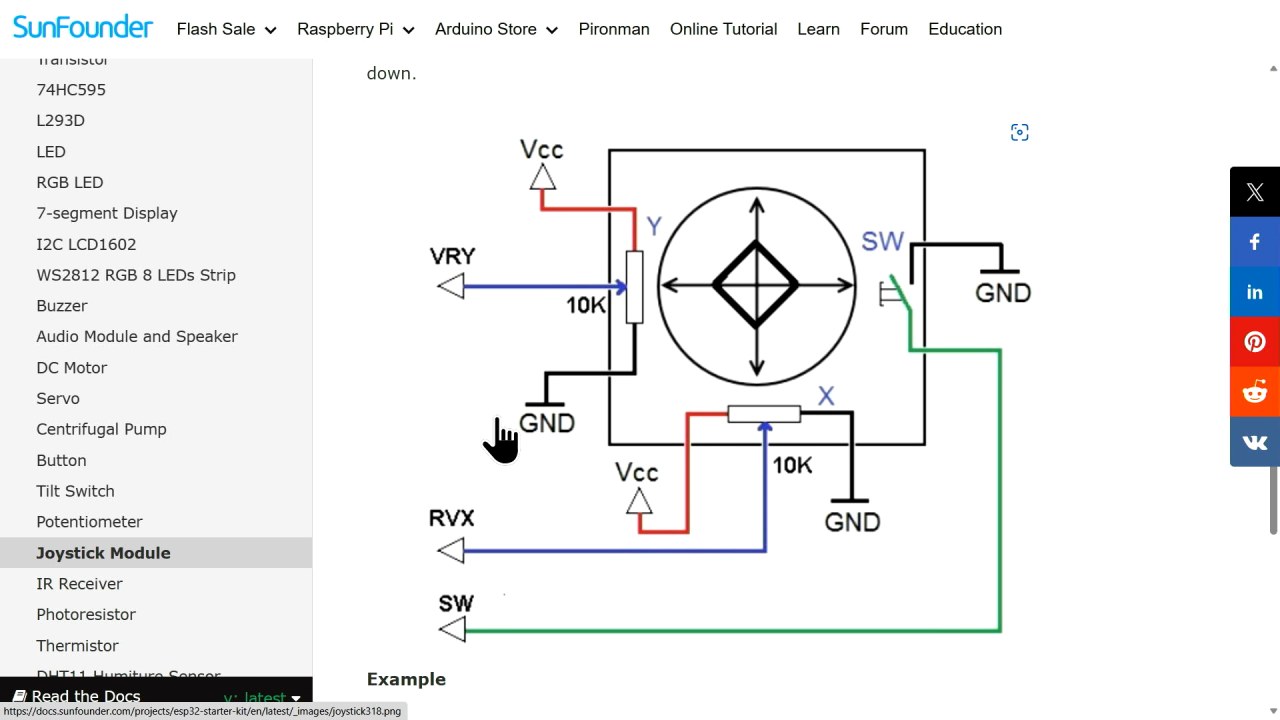
To wire the joystick to the ESP32, start by connecting the ground pin from the joystick to a ground pin on the ESP32. Next, connect the VCC pin of the joystick to the 3.3 V pin on the ESP32. The joystick has two analog output pins: connect the X-axis output (labeled as VRX) to pin 34 on the ESP32 and the Y-axis output (labeled as VRY) to pin 35.
For the switch output, connect the switch pin to pin 33 on the ESP32. This pin will read the button press as a digital input. Ensure that the connections are secure to avoid intermittent issues. If your wiring differs from the video (in video at 02:30), adapt accordingly while following the same principles for analog and digital connections.
Code Examples & Walkthrough
In the code, we begin by defining constants for the joystick pins. The identifiers xAxis, yAxis, and btn are set to 34, 35, and 33, respectively. This makes it easy to reference these pins throughout the program.
#define xAxis 34
#define yAxis 35
#define btn 33
In the setup() function, we initialize serial communication and set the button pin mode to input. This prepares the ESP32 to read data from the joystick and send it to the serial monitor.
void setup() {
  Serial.begin(115200);
  pinMode(btn, INPUT);
}
Inside the loop(), we read the analog values for the joystick's X and Y axes using analogRead() and store them in xValue and yValue. The button state is read using digitalRead() and stored in btnValue. Finally, we print these values to the serial monitor.
void loop() {
  int xValue = analogRead(xAxis);
  int yValue = analogRead(yAxis);
  int btnValue = digitalRead(btn);

  Serial.printf("Joystick value is %d , %d , %d \n",xValue,yValue,btnValue);
  delay(300);  // Delay between reads
}
This loop continuously updates the values, providing real-time feedback on joystick movement and button presses. For the complete code, please refer to the full code loaded below the article.
Demonstration / What to Expect
When the setup is complete and the code is uploaded, the serial monitor should display the X and Y values along with the button state. As you move the joystick, the values will change accordingly, reflecting its position. Pressing the button will toggle its state between high and low.
Common pitfalls include incorrect wiring, which can lead to floating inputs or no response from the joystick. Ensure that the correct pins are used and that the pull-up resistors are implemented for the switch. Watch the video for practical demonstrations of these behaviors (in video at 13:00).
Video Timestamps
- 00:00 Start
- 1:47 Introduction to XY Joystick
- 7:32 Measuring Joystick values
- 8:40 Wiring explained
- 11:06 Arduino code for Joystick with ESP32 explained
- 14:43 Selecting ESP32 board and COM port in Arduino IDE
- 16:24 Demonstration of simply usage of Joystick
- 19:20 Detecting position of joystick code with buzzer
- 21:16 Demonstration of detecting position
图像
/*
 * // 定义x轴和y轴的常量以及按钮引脚
 */
#define xAxis 34
#define yAxis 35
#define btn 33


void setup() {
 // 以115200比特每秒初始化串行通信:
  Serial.begin(115200);

 // 将按钮引脚的模式设置为输入。
  pinMode(btn, INPUT);
}

void loop() {
 // 读取 x,y 轴的模拟值
  int xValue = analogRead(xAxis);
  int yValue = analogRead(yAxis);

 // 从按钮引脚读取数字值
  int btnValue = digitalRead(btn);

 // 打印出这些值
  Serial.printf("Joystick value is %d , %d , %d \n",xValue,yValue,btnValue);

  delay(300); // 读取之间的延迟
}
Common Course Links
Common Course Files
资源与参考
-
文档ESP32 教程 26/55 - SunFounder 摇杆文档页面docs.sunfounder.com
文件📁
没有可用的文件。