ESP32 Tutorial 38/55 - Controling RGB LED from your mobile phone | SunFounder's ESP32 IoT Learning kit
In this tutorial, we'll explore how to control an RGB LED using an ESP32 module from the SunFounder ESP32 learning kit. By sending commands from your mobile device, you can change the LED color or turn it off entirely. This project harnesses the capabilities of the ESP32, leveraging built-in Wi-Fi and Bluetooth features for seamless connectivity and control.
The RGB LED consists of three individual LEDs: red, green, and blue, which can be mixed to create various colors. In this project, you will learn how to wire the RGB LED correctly and program the ESP32 to respond to Bluetooth commands. The tutorial will also guide you through the necessary code components to achieve this functionality (in video at 02:15).
Hardware Explained
The primary components for this project include the ESP32 microcontroller and the RGB LED. The ESP32 is a powerful module with built-in Wi-Fi and Bluetooth, making it ideal for IoT applications. In this project, it will act as a server to receive commands from a mobile device and control the RGB LED accordingly.
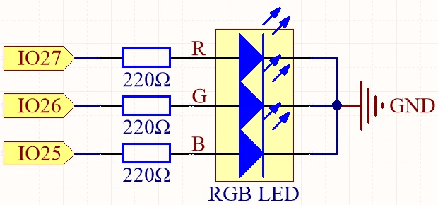
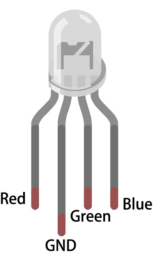
The RGB LED has four pins: one common pin (either anode or cathode) and three pins for the individual colors. The common pin connects to either the power source or ground, while the other three pins connect to the ESP32's GPIO pins through resistors to limit the current and protect the LEDs. This setup allows for precise control of each color's brightness, creating a wide range of colors.
Datasheet Details
| Manufacturer | SunFounder |
|---|---|
| Part number | RGB LED |
| Common pin type | Common anode / Common cathode |
| Forward voltage (V) | 2.0 - 3.2 V |
| Max forward current (A) | 20 mA |
| Typical current (A) | 15 mA |
| Color resolution | 8 bit (0-255) |
| Package | Through-hole / SMD |
- Ensure proper resistor values (typically 220 Ohm) to limit current through each LED channel.
- Check the common pin configuration (anode or cathode) before wiring.
- Use PWM for dimming and color mixing by adjusting the signal sent to each LED.
- Be cautious with wiring to avoid short circuits; connect one pin at a time.
- Test each color individually after setup to confirm correct wiring.
Wiring Instructions

To wire the RGB LED to the ESP32, start by placing the RGB LED on a breadboard. The longer pin is the common pin, which you will connect to either the positive voltage (for common anode) or ground (for common cathode). If you are using common anode, connect the long pin to the 3.3V pin on the ESP32. For common cathode, connect it to the GND pin.
Next, take three 220 Ohm resistors and connect one end of each resistor to the corresponding RGB pins of the LED. Connect the other ends of the resistors to the ESP32 GPIO pins: connect the red pin of the LED to GPIO 27, the green pin to GPIO 26, and the blue pin to GPIO 25. Finally, ensure that the common pin is appropriately connected based on your configuration (anode or cathode).
Code Examples & Walkthrough
The code for this project begins with defining the pins connected to the RGB LED. The following excerpt shows how the pins are declared:
const int redPin = 27;
const int greenPin = 26;
const int bluePin = 25;
Here, redPin, greenPin, and bluePin are assigned specific GPIO numbers on the ESP32 for each color channel of the RGB LED.
In the setup function, the Bluetooth is initialized, and the PWM settings are applied. This excerpt demonstrates this initialization:
void setup() {
  Serial.begin(115200);      // Initialize the serial port
  setupBLE();                // Initialize the Bluetooth BLE

  ledcAttach(redPin, freq, resolution);
  ledcAttach(greenPin, freq, resolution);
  ledcAttach(bluePin, freq, resolution);
}
This code initializes the serial communication and sets up the Bluetooth functionality while attaching the RGB LED pins to PWM channels for control.
Finally, the loop function checks for received Bluetooth messages and adjusts the LED color accordingly:
if (value == "red") {
  setColor(255, 0, 0); // Red
  Serial.println("red");
}
In this section, if the received value is "red", the LED will be set to full red brightness using the setColor function.
For a complete understanding of the code, it's recommended to watch the video tutorial where the full code is loaded below the article.
Demonstration / What to Expect
Once everything is wired and the code is uploaded, you should be able to control the RGB LED from your mobile device via Bluetooth. By sending commands like "red", "green", "blue", etc., you will see the LED change colors accordingly. If you send "LED_off", the RGB LED will turn off. Make sure to check the serial monitor for any debugging messages to confirm that commands are being received correctly (in video at 10:45).
Video Timestamps
- 00:00 Start
- 1:59 What's RGB LED?
- 6:01 RGB Color explained
- 10:01 Documentation page
- 11:19 Wiring explained
- 13:34 Selecting ESP32 board and COM port in Arduino IDE
- 15:15 Arduino Code
- 18:02 Demonstration of controlling RGB LED using your phone
图像
#include "BLEDevice.h"
#include "BLEServer.h"
#include "BLEUtils.h"
#include "BLE2902.h"

// Define RGB LED pins
const int redPin = 27;
const int greenPin = 26;
const int bluePin = 25;

// Define PWM frequency and resolution
const int freq = 5000;
const int resolution = 8;

// Define the Bluetooth device name
const char *bleName = "ESP32_Bluetooth";

// Define the received text and the time of the last message
String receivedText = "";
unsigned long lastMessageTime = 0;

// Define the UUIDs of the service and characteristics
#define SERVICE_UUID "8785d8b3-9d23-473b-aee5-3fabe2ba9583"
#define CHARACTERISTIC_UUID_RX "b2bcd13b-aab6-4660-92ae-40abf6941fce"
#define CHARACTERISTIC_UUID_TX "4219d86a-d701-4fd2-bd84-04db50f70fe2"

// Define the Bluetooth characteristic
BLECharacteristic *pCharacteristic;

void setup() {
  Serial.begin(115200);      // Initialize the serial port
  setupBLE();                // Initialize the Bluetooth BLE

  ledcAttach(redPin, freq, resolution);
  ledcAttach(greenPin, freq, resolution);
  ledcAttach(bluePin, freq, resolution);
}

void loop() {
  // When the received text is not empty and the time since the last message is over 1 second
  // Send a notification and print the received text
  if (receivedText.length() > 0 && millis() - lastMessageTime > 1000) {
    Serial.print("Received message: ");
    Serial.println(receivedText);
    pCharacteristic->setValue(receivedText.c_str());
    pCharacteristic->notify();
    receivedText = "";
  }

  // Read data from the serial port and send it to BLE characteristic
  if (Serial.available() > 0) {
    String str = Serial.readStringUntil('\n');
    const char *newValue = str.c_str();
    pCharacteristic->setValue(newValue);
    pCharacteristic->notify();
  }
}

// Define the BLE server callbacks
class MyServerCallbacks : public BLEServerCallbacks {
  // Print the connection message when a client is connected
  void onConnect(BLEServer *pServer) {
    Serial.println("Connected");
  }
  // Print the disconnection message when a client is disconnected
  void onDisconnect(BLEServer *pServer) {
    Serial.println("Disconnected");
  }
};

// Define the BLE characteristic callbacks
class MyCharacteristicCallbacks : public BLECharacteristicCallbacks {
  void onWrite(BLECharacteristic *pCharacteristic) {
    std::string value = std::string(pCharacteristic->getValue().c_str());
    if (value == "led_off") {
      setColor(0, 0, 0); // turn the RGB LED off
      Serial.println("RGB LED turned off");
    } else if (value == "red") {
      setColor(255, 0, 0); // Red
      Serial.println("red");
    }
    else if (value == "green") {
      setColor(0, 255, 0); // green
      Serial.println("green");
    }
    else if (value == "blue") {
      setColor(0, 0, 255); // blue
      Serial.println("blue");
    }
    else if (value == "yellow") {
      setColor(255, 150, 0); // yellow
      Serial.println("yellow");
    }
    else if (value == "purple") {
      setColor(80, 0, 80); // purple
      Serial.println("purple");
    }
  }
};

// Initialize the Bluetooth BLE
void setupBLE() {
  BLEDevice::init(bleName);                        // Initialize the BLE device
  BLEServer *pServer = BLEDevice::createServer();  // Create the BLE server
  // Print the error message if the BLE server creation fails
  if (pServer == nullptr) {
    Serial.println("Error creating BLE server");
    return;
  }
  pServer->setCallbacks(new MyServerCallbacks());  // Set the BLE server callbacks

  // Create the BLE service
  BLEService *pService = pServer->createService(SERVICE_UUID);
  // Print the error message if the BLE service creation fails
  if (pService == nullptr) {
    Serial.println("Error creating BLE service");
    return;
  }
  // Create the BLE characteristic for sending notifications
  pCharacteristic = pService->createCharacteristic(CHARACTERISTIC_UUID_TX, BLECharacteristic::PROPERTY_NOTIFY);
  pCharacteristic->addDescriptor(new BLE2902());  // Add the descriptor
  // Create the BLE characteristic for receiving data
  BLECharacteristic *pCharacteristicRX = pService->createCharacteristic(CHARACTERISTIC_UUID_RX, BLECharacteristic::PROPERTY_WRITE);
  pCharacteristicRX->setCallbacks(new MyCharacteristicCallbacks());  // Set the BLE characteristic callbacks
  pService->start();                                                 // Start the BLE service
  pServer->getAdvertising()->start();                                // Start advertising
  Serial.println("Waiting for a client connection...");              // Wait for a client connection
}

void setColor(int red, int green, int blue) {
  // For common-anode RGB LEDs, use 255 minus the color value
  ledcWrite(redPin, red);
  ledcWrite(greenPin, green);
  ledcWrite(bluePin, blue);
}
Common Course Links
Common Course Files
资源与参考
-
文档ESP32 教程 38/55 - SunFounder 蓝牙 RGB LED 文档页面docs.sunfounder.com
文件📁
没有可用的文件。