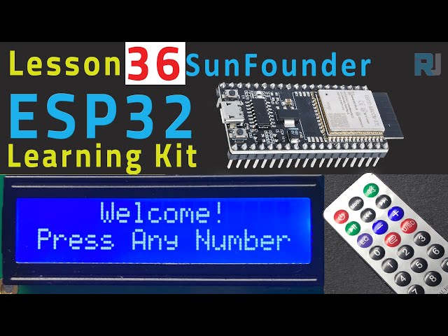
ESP32 Tutorial 36/55 - Guessing Number Game | SunFounder's ESP32 IoT Learning kit
In this tutorial, we will create a fun guessing number game using the ESP32 microcontroller along with an infrared remote and an LCD display. The player will attempt to guess a randomly generated number between 0 and 99, with the game providing hints about whether the guess is too high or too low. Through this project, you will learn how to use the infrared receiver, display values on an LCD, and manage user input from a remote control. You can refer to the video for additional clarity (in video at 00:00).


Hardware Explained
The primary components used in this project include the ESP32 microcontroller, an infrared remote control, an infrared receiver, and an LCD display. The ESP32 serves as the main processing unit and is capable of handling wireless communication, making it a versatile choice for IoT projects. The infrared remote allows users to input guesses without requiring physical interaction with the board, while the LCD displays the game status and prompts.
The infrared receiver detects signals from the remote control and decodes them for use in the game. Each button press on the remote corresponds to a specific value that the ESP32 can interpret. The LCD display provides a visual interface for the user, showing the current guess range and whether the guess was correct.
Datasheet Details
| Manufacturer | SunFounder |
|---|---|
| Part number | ESP32 |
| Logic/IO voltage | 3.3 V |
| Supply voltage | 5 V (via USB) |
| Output current (per channel) | 12 mA (max) |
| PWM frequency guidance | 1 kHz |
| Input logic thresholds | 0.3 * Vcc to 0.7 * Vcc |
| Voltage drop / RDS(on) / saturation | 0.2 V |
| Thermal limits | Operating temperature: -40 to 85 °C |
| Package | WROOM-32 module |
| Notes / variants | Supports Wi-Fi and Bluetooth |
- Ensure all components are rated for 3.3 V and 5 V where applicable.
- Use proper pull-up resistors for the IR receiver to avoid floating inputs.
- Consider using a heat sink if running at maximum output current for extended periods.
- When using PWM, maintain a frequency of around 1 kHz for optimal performance.
- Be cautious with wiring; ensure connections are secure to avoid intermittent failures.
Wiring Instructions

To set up the wiring for the guessing number game, start by connecting the infrared receiver. Connect the red wire from the right pin of the receiver to the 3.3 V power supply on the ESP32. The black wire should go to the ground, while the left pin of the infrared receiver connects to pin 14 on the ESP32.
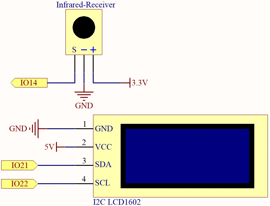
Next, wire the LCD display. Connect the VCC pin of the LCD to the 5 V supply on the ESP32 and the ground pin to ground. The SDA and SCL pins of the LCD should be connected to pins 21 and 22 respectively. Ensure that there are two empty spaces between the SDA and SCL connections to avoid pin conflicts. Finally, make sure to remove any plastic covers from the battery before powering the board.
Code Examples & Walkthrough
The following code snippets illustrate essential parts of the program used for the guessing number game. We start by including necessary libraries and defining key identifiers.
#include
#include
#include
#include

const uint16_t IR_RECEIVE_PIN = 14;
IRrecv irrecv(IR_RECEIVE_PIN);
decode_results results;
In this excerpt, we include libraries for handling the LCD and IR receiver functionality. The pin for the infrared receiver is defined as 14, and we create instances of the necessary objects to manage input and output.
void setup() {
  lcd.init();
  lcd.backlight();
  Serial.begin(9600);
  irrecv.enableIRIn();
  initNewValue();
}
This snippet shows the setup function where we initialize the LCD, start serial communication, and enable the IR receiver. The function initNewValue() is called to generate a new random number for the player to guess.
bool detectPoint() {
  if (count > pointValue) {
    if (count < upper) upper = count;
  } else if (count < pointValue) {
    if (count > lower) lower = count;
  } else if (count == pointValue) {
    count = 0;
    return 1;
  }
  count = 0;
  return 0;
}
This function checks the player's guess against the randomly generated number, adjusting the upper and lower limits accordingly. If the guess is correct, it resets the count and returns true.
The full code is loaded below the article for your reference.
Demonstration / What to Expect
Once everything is wired and the code is uploaded, the game will prompt you to press any number on the remote control. The game will then provide feedback on your guesses, updating the range of possible numbers until you correctly guess the target number. If you press the POWER button, the game resets and starts over (in video at 02:30).
Common pitfalls include ensuring that the infrared receiver is properly oriented and that all connections are secure. If the game does not respond, check the power supply and verify that the correct board and port are selected in the Arduino IDE.
Video Timestamps
- 00:00 Start
- 2:17 Introduction to the game project
- 4:37 Wiring
- 6:15 Arduino Code explained
- 12:32 Selecting ESP32 Board and COM Port in Arduino IDE
- 16:16 Playing Guessing number game
Images
#include <Wire.h>
#include <LiquidCrystal_I2C.h>
#include <IRremoteESP8266.h>
#include <IRrecv.h>

// Define the IR receiver pin
const uint16_t IR_RECEIVE_PIN = 14;

// Create an IRrecv object
IRrecv irrecv(IR_RECEIVE_PIN);

// Create a decode_results object
decode_results results;

const long interval = 1000;

unsigned long previousMillis = 0;

// Initialize the LCD object
LiquidCrystal_I2C lcd(0x27, 16, 2);

// Initialize the input number value
int count = 0;

// Initialize the random lucky point
int pointValue = 0;

// Initialize the upper and lower limit tips
int upper = 99;
int lower = 0;

void setup() {
  // Initialize the LCD screen
  lcd.init();
  lcd.backlight();

  // Start the serial communication
  Serial.begin(9600);

  // Enable the IR receiver
  irrecv.enableIRIn();

  // Initialize a new lucky point value
  initNewValue();
}

void loop() {
  // If a signal is received from the IR receiver
  if (irrecv.decode(&results)) {
    bool result = 0;
    String num = decodeKeyValue(results.value);

    // If the POWER button is pressed
    if (num == "POWER") {
      initNewValue(); // Initialize a new lucky point value
    }

    // If the CYCLE button is pressed
    else if (num == "CYCLE") {
      result = detectPoint(); // Detect the input number
      lcdShowInput(result); // Show the result on the LCD screen
    }

    // If a number button (0-9) is pressed,
    //add the digit to the input number
    //and detect the number if it is greater than or equal to 10
    else if (num >= "0" && num <= "9") {
      count = count * 10;
      count += num.toInt();
      if (count >= 10) {
        result = detectPoint();
      }
      lcdShowInput(result);
    }
    irrecv.resume();
  }
}

// Function to initialize a new lucky point value
void initNewValue() {
  // Set the random seed based on the analog value from pin A0
  randomSeed(analogRead(A0));

  // Generate a new random lucky point value
  pointValue = random(99);

  // Reset the upper and lower limit tips
  upper = 99;
  lower = 0;

  // Show the welcome message on the LCD screen
  lcd.clear();
  lcd.print("    Welcome!");
  lcd.setCursor(0, 1);
  lcd.print("Press Any Number");

  // Reset the input number value
  count = 0;

  // Print the lucky point value to the serial monitor
  Serial.print("point is ");
  Serial.println(pointValue);
}

// Detect the input number
//and update the upper/lower limit tips accordingly
bool detectPoint() {
  if (count > pointValue) {
    if (count < upper)upper = count;
  }
  else if (count < pointValue) {
    if (count > lower)lower = count;
  }

  // If the input number is equal to the lucky point value,
  else if (count == pointValue) {

    // Reset the input number and return true
    count = 0;
    return 1;
  }
  // Reset the input number and return false
  count = 0;
  return 0;
}

// Show the input number and the upper/lower limit tips
void lcdShowInput(bool result) {
  lcd.clear();

  // If the input number is equal to the lucky point value
  if (result == 1)
  {
    // Show the success message and initialize a new lucky point value
    lcd.setCursor(0, 1);
    lcd.print(" You've got it! ");
    delay(5000);
    initNewValue();
    return;
  }
  lcd.print("Enter number:");
  lcd.print(count);
  lcd.setCursor(0, 1);
  lcd.print(lower);
  lcd.print(" < Point < ");
  lcd.print(upper);
}

// Function to decode the key value from the IR receiver signal
String decodeKeyValue(long result)
{
  switch(result){
    case 0xFF6897:
      return "0";
    case 0xFF30CF:
      return "1";
    case 0xFF18E7:
      return "2";
    case 0xFF7A85:
      return "3";
    case 0xFF10EF:
      return "4";
    case 0xFF38C7:
      return "5";
    case 0xFF5AA5:
     return "6";
    case 0xFF42BD:
      return "7";
    case 0xFF4AB5:
      return "8";
    case 0xFF52AD:
      return "9";
    case 0xFF906F:
      return "+";
    case 0xFFA857:
      return "-";
    case 0xFFE01F:
      return "EQ";
    case 0xFFB04F:
      return "U/SD";
    case 0xFF9867:
      return "CYCLE";
    case 0xFF22DD:
      return "PLAY/PAUSE";
    case 0xFF02FD:
      return "BACKWARD";
    case 0xFFC23D:
      return "FORWARD";
    case 0xFFA25D:
      return "POWER";
    case 0xFFE21D:
      return "MUTE";
    case 0xFF629D:
      return "MODE";
    case 0xFFFFFFFF:
      return "ERROR";
    default :
      return "ERROR";
    }
}
Common Course Links
Common Course Files
Resources & references
-
DocumentationESP32 Tutorial 36/55- SunFounder doc page for guessing numberdocs.sunfounder.com
Files📁
No files available.