ESP32 Tutorial 35/55 - Plant Monitor, soil, temperature and light | SunFounder's ESP32 IoT Learning kit
In this tutorial, we will be building a plant monitor using the ESP32 microcontroller from the SunFounder ESP32 IoT Learning Kit. This project combines several components to monitor soil moisture, temperature, humidity, and light levels. By the end of this guide, you'll have a fully functioning system that can manage and display these critical parameters for plant care. For a detailed visual explanation, be sure to check the video (in video at 00:00).

Hardware Explained
The main components used in this project include the ESP32 microcontroller, DHT11 sensor, soil moisture sensor, light-dependent resistor (LDR), and an LCD for displaying data. The ESP32 serves as the brain of the setup, handling data processing and control tasks. It features built-in Wi-Fi and Bluetooth, providing connectivity options for remote monitoring.


The DHT11 sensor measures temperature and humidity, while the soil moisture sensor detects moisture levels in the soil. The LDR measures the ambient light intensity, allowing for insights into the plant's lighting conditions. Each component plays a crucial role in ensuring the health of the plant by providing real-time data.
Datasheet Details
| Manufacturer | SunFounder |
|---|---|
| Part number | DHT11 |
| Logic/IO voltage | 3.3 V |
| Supply voltage | 5 V |
| Output current (per channel) | 20 mA |
| Peak current (per channel) | 50 mA |
| PWM frequency guidance | N/A |
| Input logic thresholds | 0.3 VCC (low), 0.7 VCC (high) |
| Voltage drop / RDS(on) / saturation | N/A |
| Thermal limits | 0°C to 50°C |
| Package | DIP |
| Notes / variants | Compatible with DHT22 |
- Ensure proper voltage levels for each component (5V for motor driver, 3.3V for sensors).
- Use pull-down resistors for push buttons to prevent floating inputs.
- Keep wiring neat to avoid confusion and potential shorts.
- Verify connections before powering the circuit to prevent damage.
- Check the DHT11 wiring as it is sensitive to incorrect connections.
Wiring Instructions

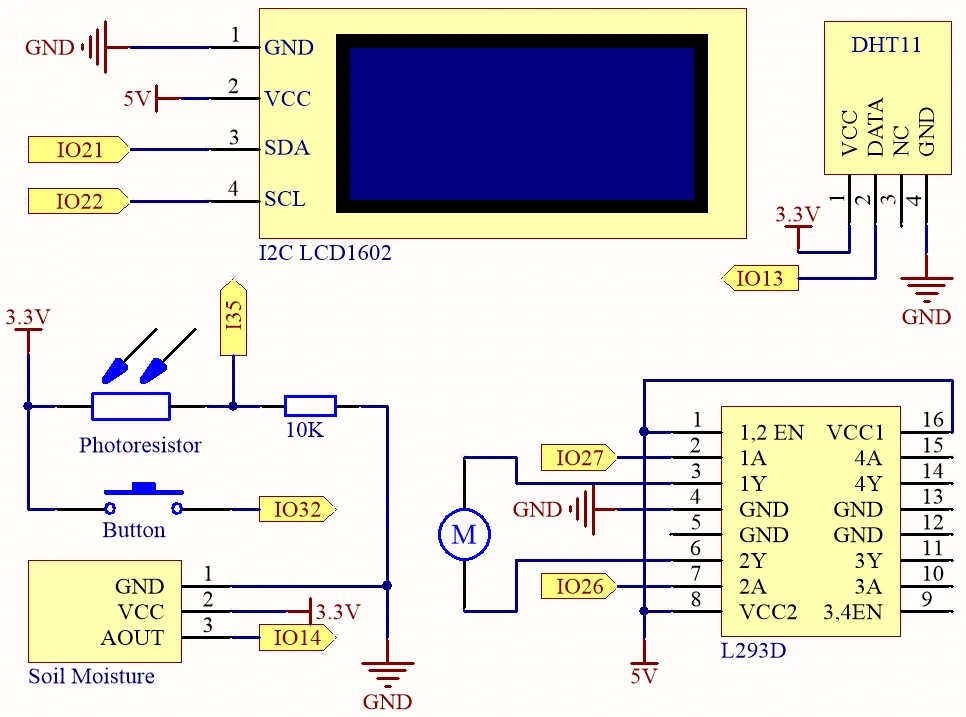
To wire the components, start by connecting the power and ground lines. The ESP32 should be powered with a lithium battery, connecting the positive terminal to the VCC line and the ground to the GND line on the breadboard. The DHT11 sensor's data pin connects to PIN 13, while its VCC goes to the 3.3V line and GND to the ground. The soil moisture sensor connects similarly: its signal pin to PIN 14, VCC to 3.3V, and GND to ground.
For the LDR, connect one pin to the 3.3V line and the other to PIN 35, with a 10k ohm resistor connected from the LDR to ground. The LCD display connects to the 5V line for power and uses SDA and SCL pins connected to PIN 21 and PIN 22, respectively. Finally, wire the push button to PIN 32 with the pull-down resistor connected to ground, ensuring it reads low when not pressed and high when pressed.
Code Examples & Walkthrough
The core of our program begins with defining the pins for each component. For example, DHTPIN is assigned to PIN 13 for the DHT11 sensor, while MOIS_PIN is set to PIN 14 for the moisture sensor. This organization helps keep track of which sensor is connected to which pin.
#define DHTPIN 13     // Set the pin connected to the DHT11 data pin
#define MOIS_PIN 14 // Soil moisture module
#define LIGHT_PIN 35 // Photoresistor
Next, we initialize the DHT sensor and the LCD display inside the setup() function. This is crucial as it prepares these components for operation. Making sure to call dht.begin() is essential for the DHT sensor to start reading values correctly.
void setup() {
  Serial.begin(115200);
  dht.begin();  // Initialize the DHT11
  lcd.init();  // Initialize the LCD
  lcd.backlight();
}
In the loop() function, we continuously read the temperature and humidity values, displaying them on the LCD. If the button is pressed, the motor is activated to water the plants. This logic uses the digital read of the button pin to determine whether to turn the motor on or off.
void loop() {
  float humidity = dht.readHumidity();
  float temperature = dht.readTemperature();
  if (digitalRead(BUTTON) == HIGH) {
    digitalWrite(motor1A, HIGH); // Turn on water pump
  } else {
    digitalWrite(motor1A, LOW); // Turn off water pump
  }
  delay(2000);
}
This code structure allows for a clear flow of data and control, ensuring that the plant monitor functions smoothly. For more details, the full code loads below the article.
Demonstration / What to Expect
Upon completing the setup and uploading the code, the LCD should display temperature and humidity readings alternately with moisture and light levels. When the push button is pressed, the water pump should activate, delivering water to the plant. Ensure that all connections are secure to avoid issues like floating inputs or incorrect readings (in video at 05:30).
Monitoring the values displayed on the LCD and serial monitor will help ensure the system functions correctly. If you encounter issues, double-check the wiring and ensure all components are powered appropriately.
Video Timestamps
- 00:00 Start
- 2:23 Project Introduction
- 4:02 Docs page
- 7:43 1-L293D Pump motor driver
- 14:30 2-Push button for Pump
- 16:35 3-DHT11 Temperature and Humidity sensor
- 19:26 4-slild Moisture Sensor
- 21:43 5-Light Sensor
- 24:47 6-Soil Moisture Sensor
- 26:01 full Plant Monitor Arduino Code
- 29:21 Demonstration
Images

#include "DHT.h"
#include <Wire.h>
#include <LiquidCrystal_I2C.h>

#define DHTPIN 13     // Set the pin connected to the DHT11 data pin
#define MOIS_PIN 14 // Soil mOisture module
#define LIGHT_PIN 35 // Photoresistor
#define motor1A 27 // Pump pin
#define motor2A 26 // Pump pin
#define BUTTON 32 // Button

#define DHTTYPE DHT11  // DHT 11
DHT dht(DHTPIN, DHTTYPE);

int page = 0;

LiquidCrystal_I2C lcd(0x27, 16, 2);

void setup() {

  Serial.begin(115200);

  // Initialize the dht11
  dht.begin();

  lcd.init();  // initialize the lcd
  lcd.backlight();
  lcd.clear();

  // initialize digital pin as an output.
  pinMode(motor1A, OUTPUT);
  pinMode(motor2A, OUTPUT);

  pinMode(BUTTON, INPUT);
}

void loop() {

  // Reading temperature or humidity takes about 250 milliseconds!
  // Sensor readings may also be up to 2 seconds 'old' (it's a very slow sensor)
  float humidity = dht.readHumidity();
  // Read temperature as Celsius (the default)
  float temperature = dht.readTemperature();

  // Check if any reads failed and exit early (to try again).
  if (isnan(humidity) || isnan(temperature)) {
    Serial.println("Failed to read from DHT sensor!");
    return;
  }

  lcd.clear();
  // Show message per 2 second
  if ((page++) % 2) {
    // Display temperature and humidity
    lcd.setCursor(0, 0);
    lcd.print("Humi: ");
    lcd.print(humidity);
    lcd.print("%");
    lcd.setCursor(0, 1);
    lcd.print("Temp: ");
    lcd.print(temperature);
    lcd.print("\xDF");
    lcd.print("C");
  } else {
    // Display moisture and light sensor values
    lcd.setCursor(0, 0);
    lcd.print("Mois: ");
    lcd.print(analogRead(MOIS_PIN));
    lcd.setCursor(0, 1);
    lcd.print("Light: ");
    lcd.print(analogRead(LIGHT_PIN));
  }
  // Water plant while button pressed
  Serial.println(digitalRead(BUTTON));
  if (digitalRead(BUTTON) == HIGH) {
    // Turn on water pump if button is pressed
    digitalWrite(motor1A, HIGH);
    digitalWrite(motor2A, LOW);
  } else {
    // Turn off water pump if button is not pressed
    digitalWrite(motor1A, LOW);
    digitalWrite(motor2A, LOW);
  }

  delay(2000);
}
Common Course Links
Common Course Files
Things you might need
-
AmazonPurchase LCD1602-I2C from Amazonamzn.to
-
eBayPurchase LCD1602-I2C from eBayebay.us
-
AliExpressPurchase 10pcs LCD1602-I2C from AliExpresss.click.aliexpress.com
Resources & references
-
DocumentationESP32 Tutorial 35/55- SunFounder doc page plant monitordocs.sunfounder.com
Files📁
Fritzing File
-
DHT11 Humitidy and Temperature Sensor (3 pins)
DHT11 Humitidy and Temperature Sensor (3 pins).fzpz0.20 MB -
LCD LCD1602-I2C module with 4 wires
LCD1602-I2C.fzpz0.01 MB