ESP32教程42/55 - 使用相机拍照并保存到Micro SD卡 CAM-1 | SunFounder的ESP32套件
在本教程中,我们将使用ESP32微控制器及其来自SunFounder的扩展板,通过摄像头拍摄照片并直接将其保存到micro SD卡上。该项目利用ESP32的内置功能(包括Wi-Fi和蓝牙)来打造一个紧凑的拍照设备。在本教程结束时,您将拥有一个可以拍摄并存储图像的工作设置,之后可以在计算机上访问这些图像。

对于那些刚接触ESP32生态系统的人来说,该套件为各种项目(包括本项目)提供了一个多功能平台。本项目使用的摄像头是OV2640,分辨率为1600x1200像素。虽然它可能无法与现代智能手机的质量相媲美,但对于基本的图像捕捉任务来说已经足够了。为了澄清任何步骤,请务必查看本教程附带的视频(视频中00:00处)。

硬件说明
本项目的主要组件包括ESP32微控制器、摄像头模块(OV2640)以及用于存储的micro SD卡。ESP32是一款功能强大的微控制器,具有集成的Wi-Fi和蓝牙功能,非常适合物联网应用。摄像头模块捕捉图像,然后由ESP32进行处理。
micro SD卡作为捕捉图像的存储介质。在此设置中,ESP32使用特定的GPIO引脚与摄像头模块通信,图像以JPEG格式保存在SD卡上。这样可以方便地稍后检索和查看照片。
- 将摄像头插入ESP32板时,请确保其方向正确。
- 使用容量为32 GB或更小的micro SD卡,以避免兼容性问题。
- 将GPIO 0连接到GND以进入编程模式。
- 注意电源供应,以避免欠压问题。
- 拍照时保持摄像头稳定,以避免图像模糊。
接线说明
要连接ESP32摄像头模块,首先确保ESP32已断电。使用以下引脚将micro SD卡模块连接到ESP32:将SD卡的CS引脚连接到ESP32的GPIO 5,MOSI连接到GPIO 23,MISO连接到GPIO 19,SCK连接到GPIO 18。接下来,按如下方式连接摄像头模块引脚:PWDN连接到GPIO 32,XCLK连接到GPIO 0,SIOD连接到GPIO 26,SIOC连接到GPIO 27。像素数据引脚Y2到Y9应按照代码中的定义连接到GPIO 5到GPIO 39。
确保正确连接接地和电源引脚。ESP32可以由套件中包含的电池供电。接线完成后,在给设备上电之前,请确保连接牢固。如果您严格按照说明操作,上传代码后应该会看到摄像头正确初始化。
代码示例与讲解


在代码中,我们首先包含必要的库并定义摄像头引脚配置。变量pictureNumber被初始化以跟踪拍摄的照片数量。
int pictureNumber = 0;

void setup() {
  WRITE_PERI_REG(RTC_CNTL_BROWN_OUT_REG, 0);  // 禁用欠压检测器
  Serial.begin(115200);
  camera_config_t config;
  // 摄像头的配置设置
  config.ledc_channel = LEDC_CHANNEL_0;
  // 其他摄像头设置...
}setup函数初始化串行通信并配置摄像头设置。配置包括诸如ledc_channel、pin_d0和xclk_freq_hz等参数,以实现最佳性能。
接下来,我们通过使用循环拍摄多张照片来处理图像捕捉过程。图像数据以基于pictureNumber的文件名保存到SD卡。
for (int shoot = 0; shoot < 5; shoot++) {
    camera_fb_t *fb = esp_camera_fb_get(); // 拍摄照片
    String path = "/picture" + String(pictureNumber) + ".jpg"; // 文件路径
    File file = fs.open(path.c_str(), FILE_WRITE); // 打开文件进行写入
    // 将图像数据写入文件
    file.write(fb->buf, fb->len);
    // 在EEPROM中更新照片编号
    EEPROM.write(0, pictureNumber);
}
此循环最多捕捉五张图像,每张图像以唯一的文件名保存。使用EEPROM允许程序记住最后的照片编号,确保每张新图像都有唯一的标识符。
演示/预期效果
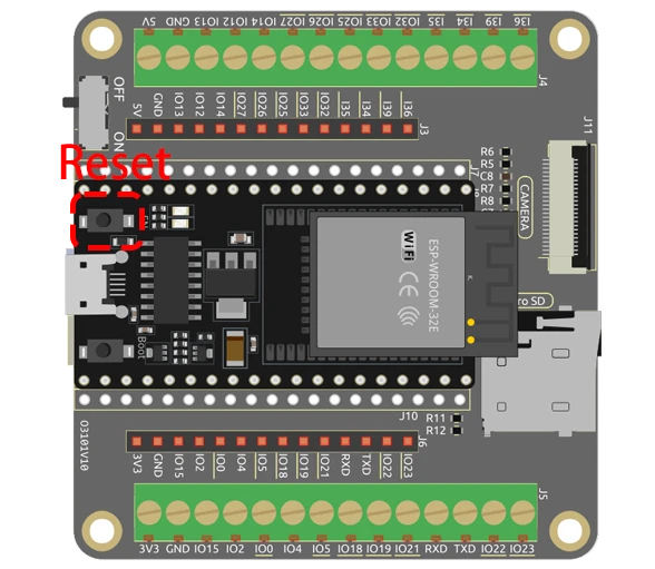
当您运行代码时,ESP32将初始化摄像头和SD卡。按下ESP32上的复位按钮后,它将拍摄一系列照片,这些照片将根据EEPROM值从0到255依次编号。拍摄图像后,您可以取出微型SD卡并在计算机上查看照片。
常见的陷阱包括确保微型SD卡已正确格式化并插入,以及保持稳定的摄像头位置以避免图像模糊。如果您遇到摄像头无法拍摄图像的问题,请仔细检查代码中设置的接线和配置(视频中06:45处)。
视频时间戳
- 00:00 开始
- 1:39 介绍
- 5:19 ESP32摄像头代码讲解
- 11:10 在Arduino IDE中选择ESP32开发板和COM端口
- 12:52 室内和室外拍照测试
图像
/*********
  Rui Santos
  Complete project details at https://RandomNerdTutorials.com/esp32-cam-take-photo-save-microsd-card

  IMPORTANT!!!
   - Select Board "AI Thinker ESP32-CAM"
   - GPIO 0 must be connected to GND to upload a sketch
   - After connecting GPIO 0 to GND, press the ESP32-CAM on-board RESET button to put your board in flashing mode

  Permission is hereby granted, free of charge, to any person obtaining a copy
  of this software and associated documentation files.
  The above copyright notice and this permission notice shall be included in all
  copies or substantial portions of the Software.
*********/

#include "esp_camera.h"
#include "Arduino.h"
#include "FS.h"                // SD Card ESP32
#include "SD_MMC.h"            // SD Card ESP32
#include "soc/soc.h"           // Disable brownour problems
#include "soc/rtc_cntl_reg.h"  // Disable brownour problems
#include "driver/rtc_io.h"
#include <EEPROM.h>  // read and write from flash memory

// define the number of bytes you want to access
#define EEPROM_SIZE 1

// Pin definition for CAMERA_MODEL_AI_THINKER
#define PWDN_GPIO_NUM 32
#define RESET_GPIO_NUM -1
#define XCLK_GPIO_NUM 0
#define SIOD_GPIO_NUM 26
#define SIOC_GPIO_NUM 27

#define Y9_GPIO_NUM 35
#define Y8_GPIO_NUM 34
#define Y7_GPIO_NUM 39
#define Y6_GPIO_NUM 36
#define Y5_GPIO_NUM 21
#define Y4_GPIO_NUM 19
#define Y3_GPIO_NUM 18
#define Y2_GPIO_NUM 5
#define VSYNC_GPIO_NUM 25
#define HREF_GPIO_NUM 23
#define PCLK_GPIO_NUM 22

int pictureNumber = 0;

void setup() {
  WRITE_PERI_REG(RTC_CNTL_BROWN_OUT_REG, 0);  //disable brownout detector

  Serial.begin(115200);
  //Serial.setDebugOutput(true);
  //Serial.println();

  camera_config_t config;
  config.ledc_channel = LEDC_CHANNEL_0;
  config.ledc_timer = LEDC_TIMER_0;
  config.pin_d0 = Y2_GPIO_NUM;
  config.pin_d1 = Y3_GPIO_NUM;
  config.pin_d2 = Y4_GPIO_NUM;
  config.pin_d3 = Y5_GPIO_NUM;
  config.pin_d4 = Y6_GPIO_NUM;
  config.pin_d5 = Y7_GPIO_NUM;
  config.pin_d6 = Y8_GPIO_NUM;
  config.pin_d7 = Y9_GPIO_NUM;
  config.pin_xclk = XCLK_GPIO_NUM;
  config.pin_pclk = PCLK_GPIO_NUM;
  config.pin_vsync = VSYNC_GPIO_NUM;
  config.pin_href = HREF_GPIO_NUM;
  config.pin_sscb_sda = SIOD_GPIO_NUM;
  config.pin_sscb_scl = SIOC_GPIO_NUM;
  config.pin_pwdn = PWDN_GPIO_NUM;
  config.pin_reset = RESET_GPIO_NUM;
  config.xclk_freq_hz = 20000000;
  config.pixel_format = PIXFORMAT_JPEG;

  if (psramFound()) {
    config.frame_size = FRAMESIZE_UXGA;  // FRAMESIZE_ + QVGA|CIF|VGA|SVGA|XGA|SXGA|UXGA
    config.jpeg_quality = 10;
    config.fb_count = 2;
  } else {
    config.frame_size = FRAMESIZE_SVGA;
    config.jpeg_quality = 12;
    config.fb_count = 1;
  }

  // Init Camera
  esp_err_t err = esp_camera_init(&config);
  if (err != ESP_OK) {
    Serial.printf("Camera init failed with error 0x%x", err);
    return;
  }

  //Serial.println("Starting SD Card");
  if (!SD_MMC.begin()) {
    Serial.println("SD Card Mount Failed");
    return;
  }

  uint8_t cardType = SD_MMC.cardType();
  if (cardType == CARD_NONE) {
    Serial.println("No SD Card attached");
    return;
  }

  // initialize EEPROM with predefined size
  EEPROM.begin(EEPROM_SIZE);
  pictureNumber = EEPROM.read(0) + 1;

  for (int shoot = 0; shoot < 5; shoot++) {
    camera_fb_t *fb = NULL;

    // Take Picture with Camera
    fb = esp_camera_fb_get();
    if (!fb) {
      Serial.println("Camera capture failed");
      return;
    }

    // Path where new picture will be saved in SD Card
    String path = "/picture" + String(pictureNumber) + ".jpg";

    fs::FS &fs = SD_MMC;
    // Serial.printf("Picture file name: %s\n", path.c_str());

    File file = fs.open(path.c_str(), FILE_WRITE);
    if (!file) {
      Serial.println("Failed to open file in writing mode");
    } else {
      file.write(fb->buf, fb->len);  // Write image data to file
      if (shoot == 4) {
        Serial.printf("Saved file to path: %s\n", path.c_str());
      }else{
        Serial.printf("Shooting... \n");
      }
      EEPROM.write(0, pictureNumber);  // Update the picture number in EEPROM
      EEPROM.commit();
    }
    file.close();                      // Close the file
    esp_camera_fb_return(fb);          // Return the frame buffer back to the camera driver
    delay(200);                        // Short delay between shots
  }
  // Turns off the ESP32-CAM white on-board LED (flash) connected to GPIO 4
  pinMode(4, OUTPUT);
  digitalWrite(4, LOW);
  rtc_gpio_hold_en(GPIO_NUM_4);

  // Put the ESP32-CAM to deep sleep
  delay(2000);
  Serial.println("Going to sleep now");
  delay(2000);
  esp_deep_sleep_start();
  Serial.println("This will never be printed");
}

void loop() {
  // Empty loop as we are putting the ESP32-CAM to deep sleep
}
Common Course Links
Common Course Files
资源与参考
-
文档ESP32教程 42/55 - SunFounder文档页面拍照docs.sunfounder.com
文件📁
没有可用的文件。