ESP32 Tutorial 49/55 - Control DC Motor Over The internet using Adafruit IoT | SunFounder's ESP32 kit
In this tutorial, we will explore how to control a DC motor over the internet using the ESP32 and the Adafruit IO MQTT service. The DC motor's speed and direction can be manipulated remotely, allowing for efficient control from anywhere with an internet connection. This project demonstrates the capabilities of the ESP32 microcontroller, which features built-in Wi-Fi, making it ideal for Internet of Things (IoT) applications.

We will be implementing a system where the motor can be started, stopped, and its speed adjusted via a web interface connected to Adafruit IO. Users can subscribe to specific topics for motor control and adjust parameters accordingly. To better understand the process, be sure to check out the video accompanying this tutorial (in video at 00:00).
Hardware Explained
For this project, we will utilize the ESP32 microcontroller, which is the heart of our system. The ESP32 is capable of handling Wi-Fi communications, making it perfect for our IoT application. It connects to the Adafruit IO platform, allowing us to send and receive messages via MQTT protocol.
Additionally, we will be using the L293D motor driver, which is essential for controlling the DC motor. The L293D can drive two DC motors and allows for control of both direction and speed through Pulse Width Modulation (PWM). It essentially acts as an interface between the ESP32 and the motor, managing the higher current required by the motor while isolating the ESP32 from any potentially damaging back-emf signals.
Datasheet Details
| Manufacturer | Texas Instruments |
|---|---|
| Part number | L293D |
| Logic/IO voltage | 4.5 - 36 V |
| Supply voltage | 4.5 - 36 V |
| Output current (per channel) | 600 mA |
| Peak current (per channel) | 1.2 A |
| PWM frequency guidance | 10 kHz (typ.) |
| Input logic thresholds | 0.8 V (high), 2.0 V (low) |
| Voltage drop / RDS(on) / saturation | 1.5 V max |
| Thermal limits | 150 °C |
| Package | DIP-16 |
| Notes / variants | Quadruple high-current half-H driver |
- Ensure proper heat sinking for continuous operation.
- Use PWM to control motor speed effectively.
- Observe input voltage limits to prevent damage.
- Check for proper ground connections between all components.
- Be cautious of back-emf; use diodes if necessary.
- Double-check wiring as polarity can affect motor direction.
- Test with a lower voltage before full operation.
- Watch for overheating during extended use.
- Make sure to debounce mechanical switches if used.
- Ensure the ESP32 is not overloaded by the motor's current.
Wiring Instructions
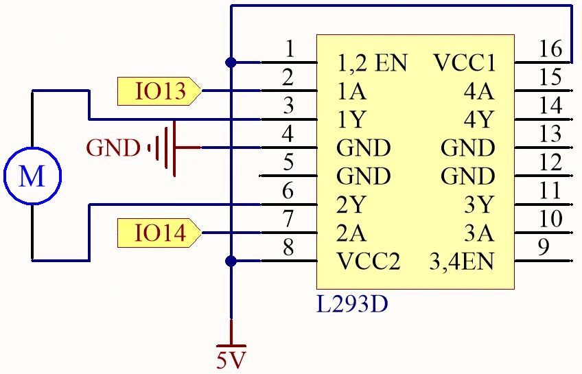
Begin by connecting the power supply. Connect the positive terminal of your external power source to the VCC pin of the L293D (pin 8) and the ground to the GND pin (pin 4). Ensure the ESP32 is powered separately if required, typically through a micro USB connection.
Next, connect the motor to the L293D. One terminal of the motor should be connected to output pin 3 (pin 2 of the L293D) and the other terminal to output pin 6 (pin 7 of the L293D). For control signals, connect pin 13 of the ESP32 to input pin 2 (pin 1 of the L293D) and pin 14 to input pin 7 (pin 2 of the L293D). The enable pin (pin 1) should also be connected to the 5V supply to activate the driver. Lastly, make sure the ESP32 ground is connected to the L293D ground for a common reference.
Code Examples & Walkthrough
The provided code initializes the necessary libraries and sets up the Wi-Fi and MQTT client. Key identifiers include motorSpeed, motorDirection, and motorStart, which manage the motor's operation based on the commands received from Adafruit IO.
bool debug = false;
#define motor1A 13
#define motor2A 14
int motorSpeed = 0;
int motorDirection = 1;
int motorStart = 1;
In this excerpt, the motor pins are defined along with initial variables for controlling speed, direction, and the start/stop state of the motor. The variable motorSpeed will be adjusted based on the input from Adafruit IO.
void setup() {
  Serial.begin(115200);
  WiFi.begin(WLAN_SSID, WLAN_PASS);
  delay(2000);
  while (WiFi.status() != WL_CONNECTED) {
    delay(500);
  }
}
In the setup function, the serial communication is initiated, and the ESP32 connects to the specified Wi-Fi network. This connection is crucial for enabling MQTT communication.
void loop() {
  MQTT_connect();
  mqtt.processPackets(500);
  runMotor();
}
This loop function establishes the MQTT connection and processes incoming packets to control the motor based on the latest commands received. The function runMotor() is called to apply the current settings to the motor.
Demonstration / What to Expect
When the setup is complete and the code is uploaded, you should be able to control the motor through the Adafruit IO dashboard. You can adjust the motor speed using a slider and change its direction with a toggle switch. If everything is wired correctly, the motor will respond to these commands in real-time, showcasing the low latency of the system (in video at 00:00).
Common issues include reversed motor direction due to incorrect wiring, so double-check connections if the motor does not behave as expected. Additionally, ensure that your MQTT topics are correctly set up in Adafruit IO to match the code.
Video Timestamps
- 00:00 Start
- 2:21 Introduction to the project
- 4:20 How DC Motor is controlled
- 6:39 L293D Motor Driver
- 11:42 What is MQTT?
- 15:03 Adafruit IO setup
- 19:17 Wiring Explained
- 22:42 Code explained
- 35:28 Project Demonstration
Images
/***********************************************************************
 This is Arduino sketch for ESP32 to DC Motor using MQTT service of Adafruit
 Watch video instruction https://youtu.be/OUgyPXNYg3g
 📚⬇️ Download and resource page https://robojax.com/RJT673
 Written By Ahamd Shamshiri
 on Feb 18, 2024

  Adafruit MQTT Library ESP32 Adafruit IO SSL/TLS example


/// ref: https://www.electronicwings.com/esp32/esp32-mqtt-client
*/
bool debug = false;
#define motor1A 13
#define motor2A 14

// PWM settings
const int freq = 500; // PWM frequency: 500 Hz
const int resolution = 8; // PWM resolution: 8 bits
const int channelA = 0; // PWM channel for motor1A: 0
const int channelB = 1; // PWM channel for motor2A: 1

char* dir[]={"CCW", "CW"};

int motorSpeed =0;
int motorDirection =1;
int motorStart = 1;
int dutyCycle =0;

#include <WiFi.h>
#include "WiFiClientSecure.h"
#include "Adafruit_MQTT.h"
#include "Adafruit_MQTT_Client.h"

/************************* WiFi Access Point *********************************/


#define WLAN_SSID "Book"
#define WLAN_PASS "88888888"

/************************* Adafruit.io Setup *********************************/

#define AIO_SERVER "io.adafruit.com"

// Using port 8883 for MQTTS
#define AIO_SERVERPORT 8883

// Adafruit IO Account Configuration
// (to obtain these values, visit https://io.adafruit.com and click on Active Key)
// #define AIO_USERNAME "YOUR_ADAFRUIT_IO_USERNAME"
// #define AIO_KEY      "YOUR_ADAFRUIT_IO_KEY"

#define AIO_USERNAME "robojax"
#define AIO_KEY "aio_jHpm60SEsWUdU5x472FViZjWzsY9"

/************ Global State (you don't need to change this!) ******************/

// WiFiFlientSecure for SSL/TLS support
WiFiClientSecure client;

// Setup the MQTT client class by passing in the WiFi client and MQTT server and login details.
Adafruit_MQTT_Client mqtt(&client, AIO_SERVER, AIO_SERVERPORT, AIO_USERNAME, AIO_KEY);


// io.adafruit.com root CA
const char* adafruitio_root_ca = \
      "-----BEGIN CERTIFICATE-----\n"
      "MIIEjTCCA3WgAwIBAgIQDQd4KhM/xvmlcpbhMf/ReTANBgkqhkiG9w0BAQsFADBh\n"
      "MQswCQYDVQQGEwJVUzEVMBMGA1UEChMMRGlnaUNlcnQgSW5jMRkwFwYDVQQLExB3\n"
      "d3cuZGlnaWNlcnQuY29tMSAwHgYDVQQDExdEaWdpQ2VydCBHbG9iYWwgUm9vdCBH\n"
      "MjAeFw0xNzExMDIxMjIzMzdaFw0yNzExMDIxMjIzMzdaMGAxCzAJBgNVBAYTAlVT\n"
      "MRUwEwYDVQQKEwxEaWdpQ2VydCBJbmMxGTAXBgNVBAsTEHd3dy5kaWdpY2VydC5j\n"
      "b20xHzAdBgNVBAMTFkdlb1RydXN0IFRMUyBSU0EgQ0EgRzEwggEiMA0GCSqGSIb3\n"
      "DQEBAQUAA4IBDwAwggEKAoIBAQC+F+jsvikKy/65LWEx/TMkCDIuWegh1Ngwvm4Q\n"
      "yISgP7oU5d79eoySG3vOhC3w/3jEMuipoH1fBtp7m0tTpsYbAhch4XA7rfuD6whU\n"
      "gajeErLVxoiWMPkC/DnUvbgi74BJmdBiuGHQSd7LwsuXpTEGG9fYXcbTVN5SATYq\n"
      "DfbexbYxTMwVJWoVb6lrBEgM3gBBqiiAiy800xu1Nq07JdCIQkBsNpFtZbIZhsDS\n"
      "fzlGWP4wEmBQ3O67c+ZXkFr2DcrXBEtHam80Gp2SNhou2U5U7UesDL/xgLK6/0d7\n"
      "6TnEVMSUVJkZ8VeZr+IUIlvoLrtjLbqugb0T3OYXW+CQU0kBAgMBAAGjggFAMIIB\n"
      "PDAdBgNVHQ4EFgQUlE/UXYvkpOKmgP792PkA76O+AlcwHwYDVR0jBBgwFoAUTiJU\n"
      "IBiV5uNu5g/6+rkS7QYXjzkwDgYDVR0PAQH/BAQDAgGGMB0GA1UdJQQWMBQGCCsG\n"
      "AQUFBwMBBggrBgEFBQcDAjASBgNVHRMBAf8ECDAGAQH/AgEAMDQGCCsGAQUFBwEB\n"
      "BCgwJjAkBggrBgEFBQcwAYYYaHR0cDovL29jc3AuZGlnaWNlcnQuY29tMEIGA1Ud\n"
      "HwQ7MDkwN6A1oDOGMWh0dHA6Ly9jcmwzLmRpZ2ljZXJ0LmNvbS9EaWdpQ2VydEds\n"
      "b2JhbFJvb3RHMi5jcmwwPQYDVR0gBDYwNDAyBgRVHSAAMCowKAYIKwYBBQUHAgEW\n"
      "HGh0dHBzOi8vd3d3LmRpZ2ljZXJ0LmNvbS9DUFMwDQYJKoZIhvcNAQELBQADggEB\n"
      "AIIcBDqC6cWpyGUSXAjjAcYwsK4iiGF7KweG97i1RJz1kwZhRoo6orU1JtBYnjzB\n"
      "c4+/sXmnHJk3mlPyL1xuIAt9sMeC7+vreRIF5wFBC0MCN5sbHwhNN1JzKbifNeP5\n"
      "ozpZdQFmkCo+neBiKR6HqIA+LMTMCMMuv2khGGuPHmtDze4GmEGZtYLyF8EQpa5Y\n"
      "jPuV6k2Cr/N3XxFpT3hRpt/3usU/Zb9wfKPtWpoznZ4/44c1p9rzFcZYrWkj3A+7\n"
      "TNBJE0GmP2fhXhP1D/XVfIW/h0yCJGEiV9Glm/uGOa3DXHlmbAcxSyCRraG+ZBkA\n"
      "7h4SeM6Y8l/7MBRpPCz6l8Y=\n"
      "-----END CERTIFICATE-----\n";

/****************************** Feeds ***************************************/

// Setup a feed called 'test' for publishing and 'test2' for subscription.
// Notice MQTT paths for AIO follow the form: <username>/feeds/<feedname>
Adafruit_MQTT_Subscribe MOTOR_SPEED = Adafruit_MQTT_Subscribe(&mqtt, AIO_USERNAME "/feeds/motor.speed");
Adafruit_MQTT_Subscribe MOTOR_DIRECTION = Adafruit_MQTT_Subscribe(&mqtt, AIO_USERNAME "/feeds/motor.direction");
Adafruit_MQTT_Subscribe MOTOR_START = Adafruit_MQTT_Subscribe(&mqtt, AIO_USERNAME "/feeds/motor.start");


/*************************** Sketch Code ************************************/


void setup() {
  // Set up PWM
  ledcSetup(channelA, freq, resolution);
  ledcSetup(channelB, freq, resolution);

  // Attach PWM channels to GPIO pins
  ledcAttachPin(motor1A, channelA);
  ledcAttachPin(motor2A, channelB);

  Serial.begin(115200);
  delay(10);

  Serial.println(F("DC Motor over MQTT EXample"));

  // Connect to WiFi access point.
  Serial.println();
  Serial.println();
  Serial.print("Connecting to ");
  Serial.println(WLAN_SSID);

  delay(1000);

  WiFi.begin(WLAN_SSID, WLAN_PASS);
  delay(2000);

  while (WiFi.status() != WL_CONNECTED) {
    delay(500);
    Serial.print(".");
  }
  Serial.println();

  Serial.println("WiFi connected");
  Serial.println("IP address: ");
  Serial.println(WiFi.localIP());

  // Set Adafruit IO's root CA
  client.setCACert(adafruitio_root_ca);

  // register callback for feed
  MOTOR_SPEED.setCallback(MOTOR_SPEED_Callback);
  // Setup MQTT subscription for time feed.
  mqtt.subscribe(&MOTOR_SPEED);

  // register callback for feed
  MOTOR_DIRECTION.setCallback(MOTOR_DIRECTION_Callback);
  // Setup MQTT subscription for time feed.
  mqtt.subscribe(&MOTOR_DIRECTION);

  // register callback for feed
  MOTOR_START.setCallback(MOTOR_START_Callback);
  // Setup MQTT subscription for time feed.
  mqtt.subscribe(&MOTOR_START);

}

// uint32_t x=0;


void loop() {

  // Ensure the connection to the MQTT server is alive (this will make the first
  // connection and automatically reconnect when disconnected).  See the MQTT_connect
  // function definition further below.
  MQTT_connect();


  // Serial.print("Speed: ");
  // Serial.print (motorSpeed);
  // Serial.print(" Dir: ");
  // Serial.print (dir[motorDirection]);
  // Serial.print(" Sart: ");
  // Serial.println(motorStart);

  // Serial.print("DutyCycle: ");
  // Serial.println(dutyCycle);

  // wait 0.5 seconds for subscription messages
  mqtt.processPackets(500);

   runMotor();//very important
  // wait a couple seconds to avoid rate limit
  //delay(2000);
}

void MOTOR_SPEED_Callback(char* message, uint16_t len) {
  char messageBuffer[40];
  //snprintf(messageBuffer, sizeof(messageBuffer), "Color status is :: %s, len :: %u", message, len);
  //Serial.println(messageBuffer);
  Serial.println(message);
  String inString = message;//sotre the message to String

  motorSpeed  =  inString.toInt();//convert the message to Integer
  if(motorSpeed >100 || motorSpeed < 0)
  {
    motorSpeed = 0;
  }
  dutyCycle = map (motorSpeed, 0, 100, 0, 255);

}


void MOTOR_DIRECTION_Callback(char* message, uint16_t len) {
  char messageBuffer[40];
  //snprintf(messageBuffer, sizeof(messageBuffer), "Color status is :: %s, len :: %u", message, len);
  //Serial.println(messageBuffer);
  Serial.println(message);
  String inString = message;//sotre the message to String

  motorDirection  =  inString.toInt();//convert the message to Integer


}


void MOTOR_START_Callback(char* message, uint16_t len) {
  char messageBuffer[40];
  //snprintf(messageBuffer, sizeof(messageBuffer), "Color status is :: %s, len :: %u", message, len);
  //Serial.println(messageBuffer);
  Serial.println(message);

  String inString = message;//sotre the message to String

  motorStart  =  inString.toInt();//convert the message to Integer


}


void runMotor()
{

  if(motorStart ==1)
  {
      if(debug)
      {
        Serial.print("Motor running:");
        Serial.print(dir[motorDirection]);
        Serial.print(" at ");
        Serial.print(motorSpeed);
        Serial.println("%");
      }
    if(motorDirection)
    {
      ledcWrite(channelA, dutyCycle);
      ledcWrite(channelB, 0);
      delay(50);
    }else{

      ledcWrite(channelA, 0);
      ledcWrite(channelB, dutyCycle);
      delay(50);
    }
  }else{
    if(debug)
    {
      Serial.println("***Motor Stopped***");
    }
      ledcWrite(channelA, 0);
      ledcWrite(channelB, 0);
  }

}//runMotor() end

// Function to connect and reconnect as necessary to the MQTT server.
// Should be called in the loop function and it will take care if connecting.
void MQTT_connect() {
  int8_t ret;
  // Stop if already connected.
  if (mqtt.connected()) {
    return;
  }
  Serial.print("Connecting to MQTT... ");
  uint8_t retries = 3;
  while ((ret = mqtt.connect()) != 0) {  // connect will return 0 for connected
    Serial.println(mqtt.connectErrorString(ret));
    Serial.println("Retrying MQTT connection in 5 seconds...");
    mqtt.disconnect();
    delay(5000);  // wait 5 seconds
    retries--;
    if (retries == 0) {
      // basically die and wait for WDT to reset me
      while (1)
        ;
    }
  }
  Serial.println("MQTT Connected!");
}
Common Course Links
Common Course Files
Resources & references
No resources yet.
Files📁
No files available.